Lighting unit

a technology of lighting units and light tubes, which is applied in the direction of transportation and packaging, semiconductor devices for light sources, lighting and heating apparatus, etc., can solve the problems of difficult or impossible to realize the weight saving of lighting units, difficult to design the layout of lamps, etc., and achieve the effect of light saving, small thickness, and light weigh

Active Publication Date: 2012-07-26
STANLEY ELECTRIC CO LTD
View PDF0 Cites 44 Cited by
  • Summary
  • Abstract
  • Description
  • Claims
  • Application Information

AI Technical Summary

Benefits of technology

[0019]The lighting unit using a lens body which is smaller in thickness and lighter in weight than a conventional lens body can be provided to achieve efficiency of use of light comparable to or higher than efficiency achieved by the conventional lens body.

Problems solved by technology

However, arrangement of an optical axis AX1 of the lens body 210 and an optical axis AX2 of the LED light source 220 crossing each other at right angles (see FIG. 1B) can make the layout design of a lamp difficult.
This makes the lens body 210 have a greater thickness accordingly, making it difficult or impossible to realize weight saving of the lighting unit 200.

Method used


Image

  • Lighting unit
  • Lighting unit
  • Lighting unit

Examples


Embodiment Construction

[0030]A description will now be made below to exemplary lighting units of the presently disclosed subject matter with reference to the accompanying drawings in accordance with exemplary embodiments.

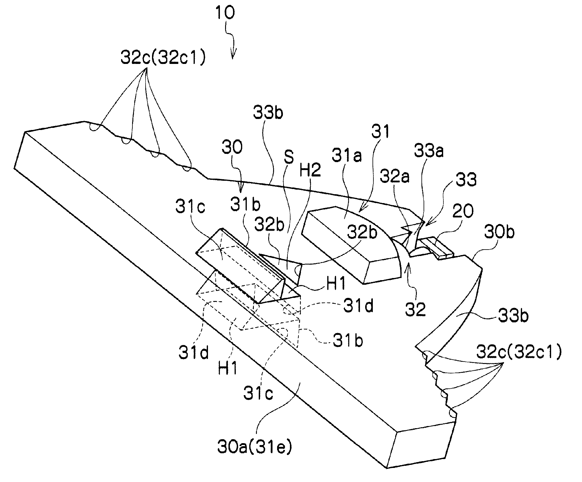
[0031]FIG. 3 is a perspective view of a lighting unit 10 as viewed from the front. FIG. 4 is a perspective view of the lighting unit 10 as viewed from the back. FIG. 5 is a front view of the lighting unit 10. FIGS. 6 and 7 are cross-sectional views of the lighting unit 10 taken along lines B-B and A-A of FIG. 5, respectively.

[0032]The lighting unit 10 of the embodiment can be applied to a vehicle-mounted signal lamp and to a generally used illumination lamp. Examples of such a vehicle-mounted signal lamp include a rear position lamp, a stop lamp, a turn signal lamp, a daytime running lamp, and a position lamp. As shown in FIGS. 3, 4 and other figures, the lighting unit 10 can include an LED light source 20 and a lens body 30.

[0033][LED Light Source 20]

[0034]The LED light source 20 can be ...


PUM


Abstract

A lighting unit can include an LED light source, and a lens body light exiting surface greater in width than in thickness. The lens body can include a first optical system, a second optical system, and a third optical system. The first optical system can include: a lens section; a first light incident surface; a first total reflection surface; and a second total reflection surface. The second optical system can include: a second light incident surface; a third total reflection surface; and a fourth total reflection surface. The third optical system can include a third light incident surface and a fifth total reflection surface. The optical systems can direct light emitted by the source at wide or narrow angles to exit the lens body substantially parallel to the optical axis. A space can be formed between the lens section and the first light incident surface.

Description

[0001]This application claims the priority benefit under 35 U.S.C. §119 of Japanese Patent Application No. 2011-012298 filed on Jan. 24, 2011, which is hereby incorporated in its entirety by reference.TECHNICAL FIELD [0002]The presently disclosed subject matter relates to a lighting unit, and more specifically, to a lighting unit including an LED light source and a plate-like lens body used in combination.BACKGROUND ART [0003]A lighting unit including an LED light source and a plate-like lens body used in combination has conventionally been suggested (see, for example, Japanese Patent No. 4458359 which is hereinafter called patent literature 1).[0004]As shown in FIGS. 1A to 1C, a lighting unit 200 disclosed in Patent Literature 1 can include a plate-like lens body 210, and an LED light source 220 arranged to face the front surface of the lens body 210. The lens body 210 can have a first side surface 211 functioning as a light exiting surface having a substantially rectangular shape ...

Claims


Application Information

Patent Timeline
Patent Type & Authority Applications(United States)
IPC IPC(8): F21V5/04
CPCF21S48/115F21S48/1241F21S48/215F21S48/2243F21Y2101/02F21S48/2262F21S48/2287F21V5/04F21V7/0091F21S48/225F21S41/24F21S41/322F21S43/14F21S43/239F21S43/241F21S43/243F21S43/247F21S43/315F21Y2115/10
Inventor OKADA, HIDETAKA
Owner STANLEY ELECTRIC CO LTD
Why Eureka
Try Eureka