Fan assembly

Active Publication Date: 2012-07-26
DELTA ELECTRONICS INC
View PDF3 Cites 21 Cited by
  • Summary
  • Abstract
  • Description
  • Claims
  • Application Information

AI Technical Summary

Benefits of technology

[0013]In an embodiment, the channel structure includes at least one guide channel adjacent to the centrifugal fan. The speed of the airflow generated by the centrifuga

Problems solved by technology

Thus, it is very dangerous; especially if children touch the rotating blades.
However, the abo

Method used


Image

  • Fan assembly
  • Fan assembly
  • Fan assembly

Examples


Embodiment Construction

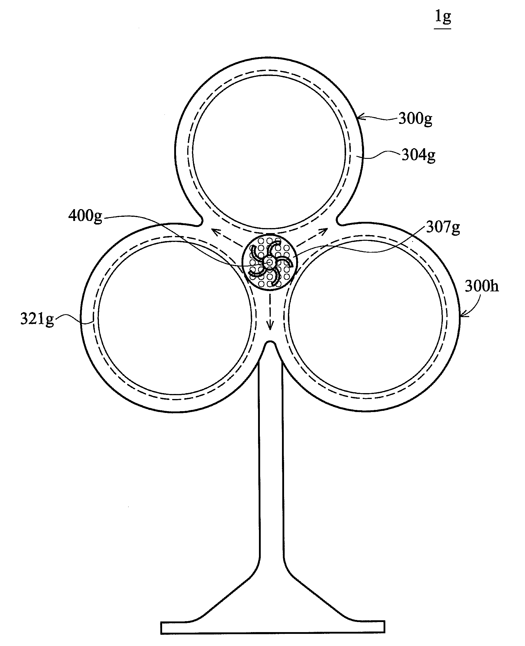
[0044]Referring to FIGS. 3 and 4, a fan assembly 1 includes a base 200, a channel structure 300 and a centrifugal fan 400. The base 200 can be disposed on the ground or a table. The channel structure 300 is supported by the base 200. The channel structure 300 includes a housing 300′ and at least a slit 321. The housing 300′ is a hollow annular structure. The housing 300′ has an accommodating space 307 and a flow channel 304 therein. The flow channel 304 and accommodating space 307 are adjacent to each other. The slit 321 is extended along the flow channel 304. The flow channel 304 is communicated with the outside of the housing 300′ via the slit 321. The centrifugal fan 400 is disposed in the accommodating space 307. The centrifugal fan 400 draws air along an axial direction D3, and generates an airflow to the flow channel 304 along an radial direction D3a. Next, the airflow flows out of the housing 300′ via the slit 321.

[0045]The housing 300′ of the channel structure 300 further in...


PUM


Abstract

A fan assembly includes a channel structure and a centrifugal fan. The channel structure includes a housing and at least a slit. The housing has an accommodating space and a flow channel adjacent to each other. The slit is extended along the flow channel. The flow channel is communicated with the outside of the housing via the slit. The centrifugal fan is disposed in the accommodating space. The centrifugal fan draws air along an axial direction and generates an airflow. The airflow flows into the flow channel along a radial direction, and flows out to the outside of the housing via the slit.

Description

CROSS-REFERENCE TO RELATED APPLICATIONS[0001]This Application claims priority of Taiwan Patent Application No. 100102548, filed on Jan. 25, 2011, the entirety of which is incorporated by reference herein.BACKGROUND OF THE INVENTION[0002]1. Field of the Invention[0003]The invention relates to a fan assembly, and in particular, to a fan assembly utilizing a centrifugal fan to generate an airflow to a channel structure, wherein the airflow flows out from the channel structure.[0004]2. Description of the Related Art[0005]A conventional household fan utilizes a motor to drive an axial-flow fan to rotate, and then an airflow is generated by the rotating axial-flow fan. The household fan has large blades to generate enough airflow. However, the larger blades have greater torque, and an extending direction and a rotating direction of the blade have an acute angle therebetween. Thus, it is very dangerous; especially if children touch the rotating blades.[0006]To solve the above problem, US P...

Claims


Application Information

Patent Timeline
IPC IPC(8): F01D25/24
CPCF04F5/16F04D25/08
Inventor CHANG, SHUN-CHEN
Owner DELTA ELECTRONICS INC
Why Eureka
Try Eureka