Burner

a burner and burner technology, applied in the field of burners, can solve the problems of unstable flame stability and burnout, difficult safe operation, and inability to make safe operation

Inactive Publication Date: 2012-07-26
LINDE AG
View PDF4 Cites 3 Cited by
  • Summary
  • Abstract
  • Description
  • Claims
  • Application Information

AI Technical Summary

Benefits of technology

[0015]The first and second fuel feed as well as the first and second oxidant feed are preferably arranged coaxially to each other. Instead of the parallel guidance of the fuel and oxidant flow, the fuel and the oxidant can also be joined at a certain angle in order to improve the intermixing of the flows.
[0036]Preferentially the flow velocity of the second oxygen-containing flow fed in via the second oxidant feed exceeds the flow velocity of the fuel flow fed in via the second fuel feed by more than 50%, preferentially by more than 75%, particularly preferably the flow velocity of the second oxygen-containing flow amounts to between 90% and 120% of the flow velocity of the second fuel flow. The flow velocity of the second oxygen-containing flow amounts to 1.5 times to 2.5 times the flow velocity of the second fuel flow, preferably approximately double the flow velocity of the second fuel flow. Through the different flow velocities shearing forces occur between the two adjacent flows, which result in an improved intermixing of the fuel with the oxidant.

Problems solved by technology

Thus, with burners operated with solid or liquid fuels, problems occur with the flame stability and the burnout, that is the complete combustion, of the fuel.
The flame detaches or is unstable and thus does not make safe operation.
A safe setting of the flame with different burner outputs and fuels is hardly possible.

Method used


Image

  • Burner
  • Burner

Examples


Embodiment Construction

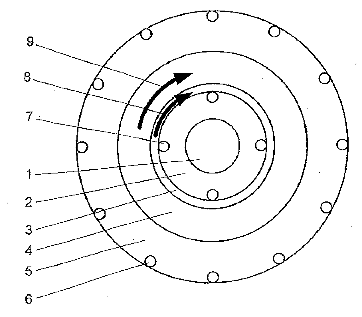
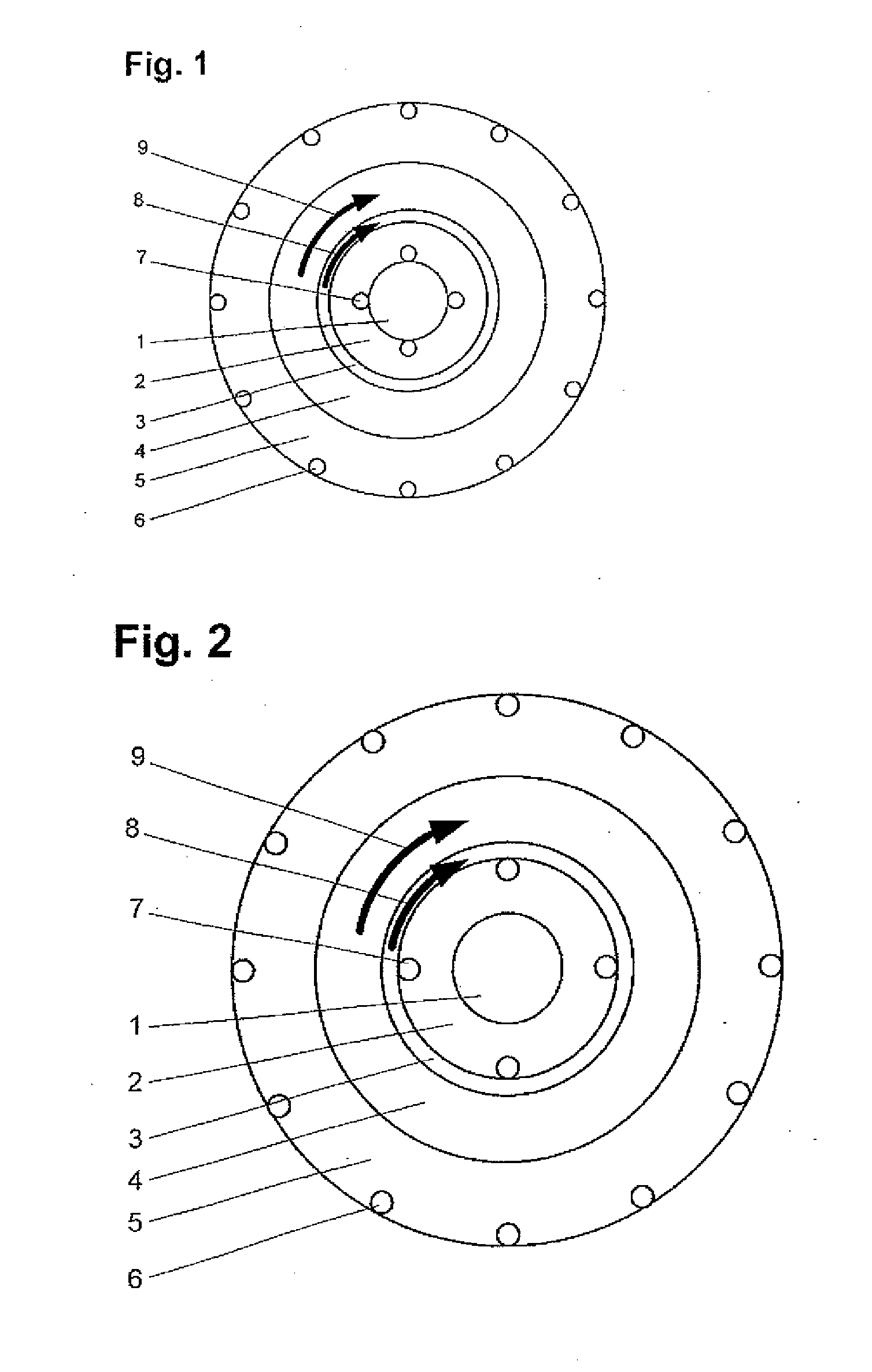
[0041]The burner shown in FIG. 1 is for the combustion of low-calorific fuels, for example of a mixture of wood and coal. The burner has a plurality of tubes of different diameter arranged coaxially to each other, wherein the central tube 1 and the ring gaps 2, 3, 4, 5 forming between the other tubes serve as fuel or oxidant feed. The tubes are orientated parallel to one another so that the flows fed in to each also exit the tube 1 or the ring gaps 2, 3, 4, 5 parallel to one another.

[0042]The tubes 1, 3 are for the feeding of fuel. A fuel source is connected to the central tube 1 and the ring gap 3 from which the tube 1 serving as first fuel feed and the ring gap 3 serving as second fuel feed are supplied with fuel. In the ring gap 3, means for generating a swirl flow are provided. To this end, flow channels are provided in the ring gap 3 which are tangentially inclined against the main flow direction, i.e. against the axial extension of the burner or of the tube 1, and the gaps 2, ...


PUM

PropertyMeasurementUnit
calorific valueaaaaaaaaaa
flow velocityaaaaaaaaaa

Abstract

A burner includes a first fuel feed and a first oxidant feed surrounding the first fuel feed in the shape of a ring. The burner includes a second fuel feed arranged about the first oxidant feed in the shape of a ring, and a second oxidant feed arranged about the second fuel feed in the shape of a ring. In addition, a plurality of oxygen lances are provided, which have a smaller radial distance from the burner centre than the second fuel feed.

Description

[0001]The invention relates to a burner with a first fuel feed and with a first oxidant feed surrounding the first fuel feed in the shape of a ring. Furthermore, the invention relates to a method for the chemical conversion of a fuel with an oxygen-containing gas by means of a burner, wherein the fuel is fed in via the burner and converted with a first flow of an oxygen-containing gas surrounding the fuel flow.[0002]During the combustion of a fuel gas with an oxygen-containing gas in externally mixing burners, that is in burners in which the fuel gas and the oxygen-containing gas are not pre-mixed but separately conducted in a mixing zone and ignited therein, it is important to achieve an intensive mixing of the oxygen-containing gas and of the fuel gas in order to accelerate the chemical combustion reaction between these gases and obtain a stable flame. This is particularly true when low-calorific fuels are employed.[0003]Thus, with burners operated with solid or liquid fuels, prob...

Claims


Application Information

Patent Timeline
Patent Type & Authority Applications(United States)
IPC IPC(8): F23D14/24F23D1/02
CPCF23C6/047Y02E20/344F23C2900/07021F23D1/005F23D11/38F23D14/24F23D14/32F23L7/007F23L2900/07007C21C5/5217F23D1/00F23D11/101F23D14/22F23D2900/01001F27D99/0033Y02E20/322F23C2201/20Y02E20/34Y02P10/20Y02P10/32
Inventor NIEHOFF, THOMAS
Owner LINDE AG
Why Eureka
Try Eureka