
Thermal Power Plant with Carbon Dioxide Capture Scrubbing Equipment

a carbon dioxide and steam turbine technology, applied in the direction of steam turbines, machines/engines, propulsion parts, etc., can solve the problems of reducing the efficiency large steam needs to be supplied by the reboiler, so as to reduce the efficiency and output of the steam turbine, reduce the energy cost, and reduce the effect of carbon dioxide capture equipmen

Inactive Publication Date: 2012-08-02
MITSUBISHI HITACHIPOWER SYST LTD
View PDF11 Cites 24 Cited by
  • Summary
  • Abstract
  • Description
  • Claims
  • Application Information

AI Technical Summary

Benefits of technology

[0010]An object of the present invention is to provide a thermal power plant comprising carbon dioxide capture scrubbing equipment that can suppress reductions in the efficiency and output of the steam turbine, and at the same time, regardless of variations in the amount of heated steam supplied from a solar heat collection apparatus to the reboiler, minimize variations in the temperature and pressure of steam generated by a reboiler and stably carry out reactions for separating carbon dioxide from an absorbent in a regeneration tower.
[0012]According to the present invention, hence solar thermal energy which requires low energy cost is utilized, the amount of extraction steam supplied from the steam turbine to the reboiler of the regeneration tower included in the carbon dioxide capture scrubbing equipment can be reduced. Therefore, reduction in the efficiency and output of the steam turbine can be suppressed.
[0013]In addition, a thermal power plant comprising carbon dioxide capture scrubbing equipment that can, regardless of variations in the amount of heated steam supplied from a solar heat collection apparatus to the reboiler, minimize variations in the temperature and pressure of steam generated by a reboiler and stably carry out reactions for separating carbon dioxide from an absorbent in a regeneration tower, can be provided.

Problems solved by technology

However, a large amount of steam needs to be supplied by the reboiler.
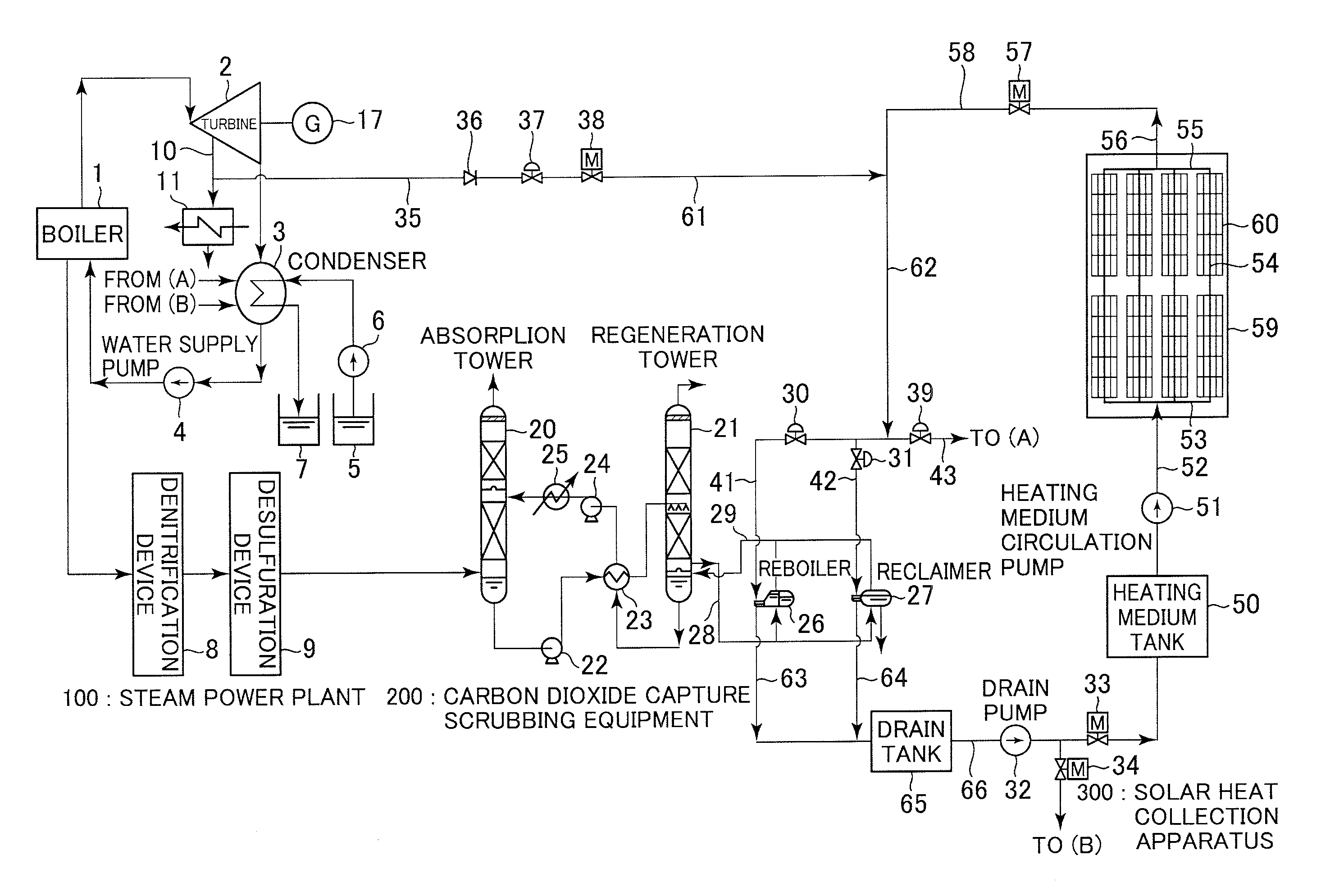
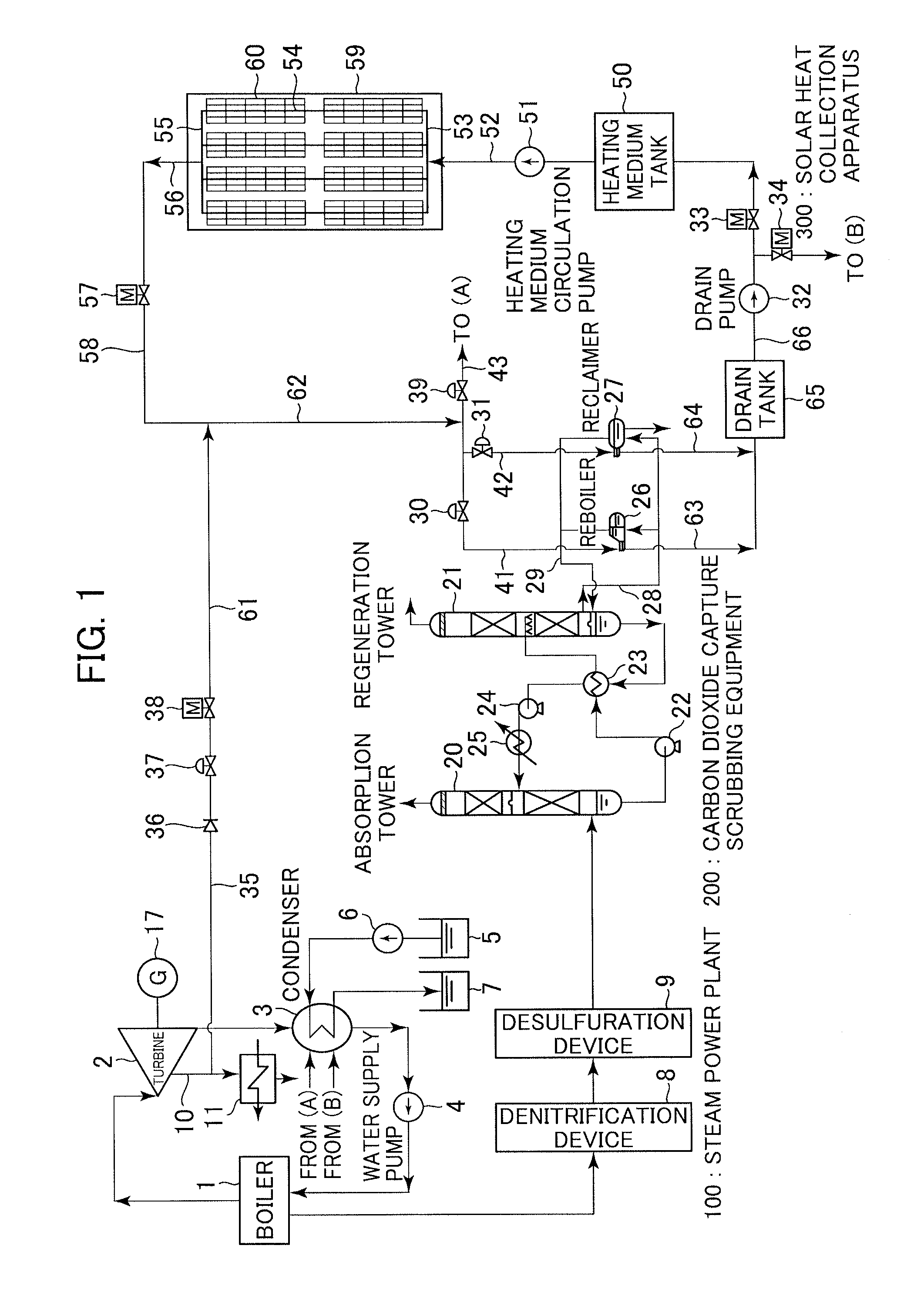
However, this reduces output of the steam turbine by an amount corresponding to the steam supplied from the extraction system, which leads to a reduced turbine efficiency.

Method used


Image

  • Thermal Power Plant with Carbon Dioxide Capture Scrubbing Equipment
  • Thermal Power Plant with Carbon Dioxide Capture Scrubbing Equipment
  • Thermal Power Plant with Carbon Dioxide Capture Scrubbing Equipment

Examples


Embodiment Construction

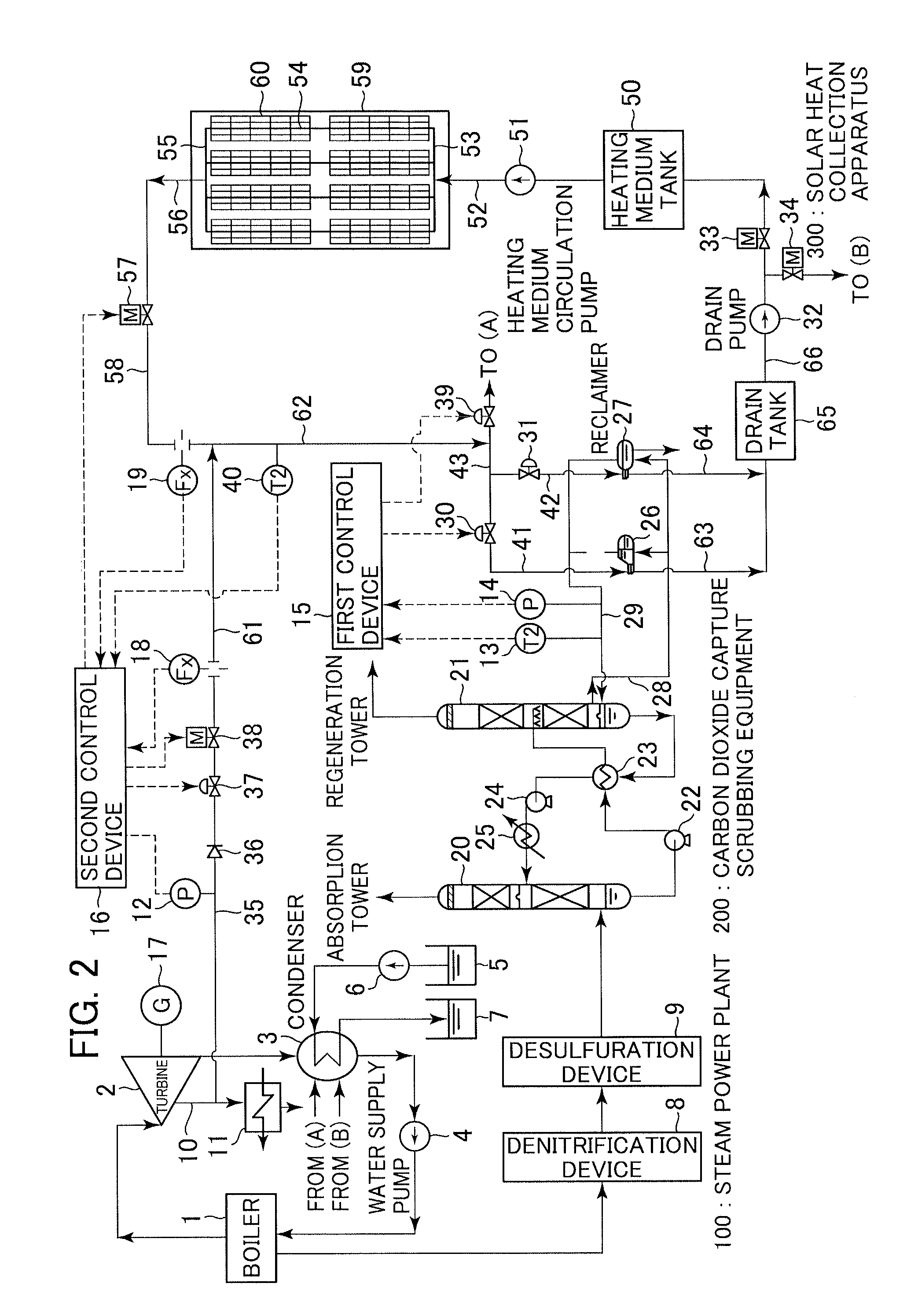
[0016]An embodiment of the present invention that is a thermal power plant provided with carbon dioxide capture scrubbing equipment that uses solar thermal energy is described below with reference to the accompanying drawings. In the drawings, equivalent constituent elements are indicated by the same reference numerals.

[0017]As the embodiment of the present invention, an example where the present invention is applied to a steam power plant which is one form of thermal power generation is described below. In this embodiment, water is used as a heating medium for collecting solar thermal energy.

[0018]FIG. 1 is an explanatory drawing showing a system of the thermal power plant according to the embodiment that includes carbon dioxide capture scrubbing equipment. A steam power plant 100 of this embodiment is shown in FIG. 1. The steam power plant 100 includes: a boiler 1 for burning fossil fuel to generate steam; a steam turbine 2 that is rotary driven by the steam generated by the boile...


PUM


Abstract

A thermal power plant includes carbon dioxide capture scrubbing equipment that suppresses reductions in the efficiency and output of a steam turbine, and, at the same time, reduces variations in the amount of steam supplied from a solar heat collection apparatus to a reboiler and variations in the temperature and pressure of reboiler generated steam, and stably carries out reactions for separating carbon dioxide from an absorbent by heating. The thermal power plant includes the carbon dioxide capture scrubbing equipment for capturing carbon dioxide from a boiler exhaust gas and the solar heat collection apparatus. Steam generated by the solar heat collection apparatus is supplied to the reboiler provided for a regeneration tower of the carbon dioxide capture scrubbing equipment.

Description

BACKGROUND OF THE INVENTION[0001]1. Field of the Invention[0002]The present invention relates to a thermal power plant, and more particularly to a fossil fuel-fired thermal power plant that includes carbon dioxide capture scrubbing equipment and a solar heat collection apparatus.[0003]2. Description of the Related Art[0004]As an example of a fossil fuel-fired thermal power plant equipped with carbon dioxide capture scrubbing equipment, there is a plant having a high pressure turbine, an intermediate pressure turbine, and a low pressure turbine, and also comprising carbon dioxide capture scrubbing equipment (Post Combustion CO2 Capture (PPC)) that includes: steam turbine equipment driven by steam generated by a fossil fuel-fired boiler, e.g., a coal-fired boiler; an absorption tower for absorbing and removing carbon dioxide from combustion exhaust gas discharged from the boiler by using a carbon dioxide absorbent; a regeneration tower for regenerating the carbon dioxide absorbent tha...

Claims


Application Information

Patent Timeline
IPC IPC(8): F01K13/00F01K17/00F01K9/00F03G6/00F01K11/02C01B32/50
CPCB01D53/1425B01D53/1475B01D2257/302B01D2257/404B01D2258/0283Y02E10/46F01K13/00F22B1/006Y02C10/04Y02C10/06B01D2259/65F01K13/02F01K17/02F22B33/14F22B33/18Y02C20/40Y02E20/32
Inventor MISHIMA, NOBUYOSHISUGIURA, TAKASHISAKAKURA, TOSHIHIKO
Owner MITSUBISHI HITACHIPOWER SYST LTD
Learn More