
Watercraft device

a technology for watercraft and hulls, applied in the direction of floating buildings, vessel safety, non-magnetic metal hulls, etc., can solve the problems of higher propulsion power requirements, higher fuel consumption, device drag, etc., to reduce the resistance of the whole device, reduce the effect of action and reduce the siz

Active Publication Date: 2012-08-02
BRIZZOLARA STEFANO
View PDF2 Cites 13 Cited by
  • Summary
  • Abstract
  • Description
  • Claims
  • Application Information

AI Technical Summary

Benefits of technology

[0016]So the profile of the hulls is changed in order to reduce its drag, maintaining the good stability in rough seas and at the same time to decrease the resistance force that the waves exert on the hull, so increasing the maximum speed of the vessel and keeping consumption under control.
[0038]In another embodiment, in order to further reduce the motion of the whole device in waves, each lateral hull can be provided with at least one active fin stabilizer that extends from the outer surface of each of the two side hulls in a direction substantially parallel to the horizontal plane of the device.

Problems solved by technology

Despite high stability in sea waves provided by the above described configuration, SWATH devices have the disadvantage of higher propulsion powering requirements, especially at high speeds and hence have higher fuel consumptions.
In fact, compared to equivalent mono-hulls or catamarans, these devices experience more drag when moving at a given speed in calm water or, conversely, with a given propulsion power they reach a lower speed.

Method used


Image

  • Watercraft device
  • Watercraft device
  • Watercraft device

Examples


Embodiment Construction

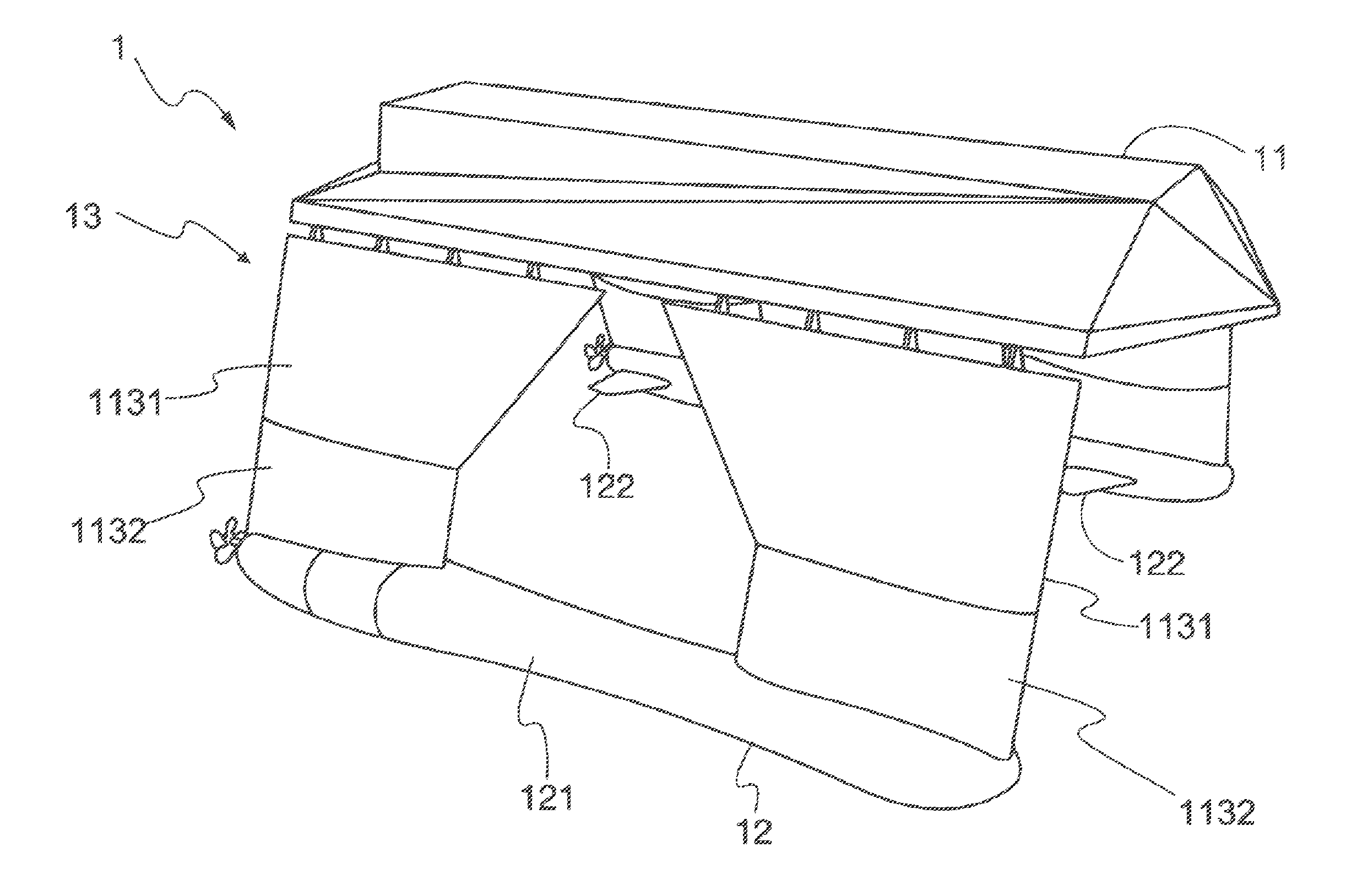
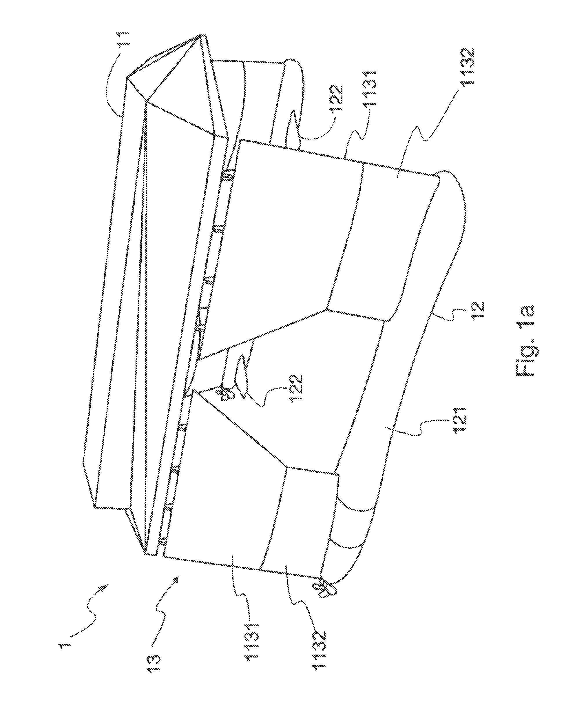
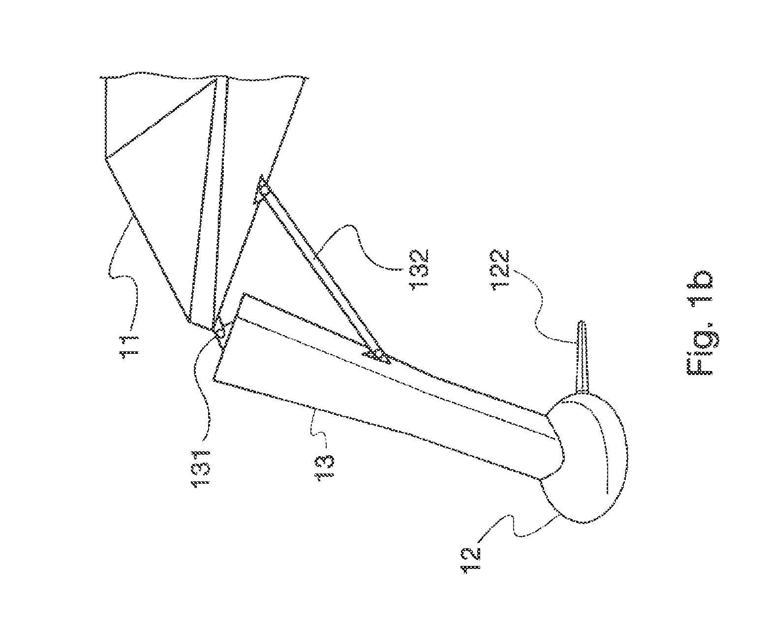
[0053]With particular reference to FIGS. 1a and 1b, a watercraft device 1 according to an embodiment of the present invention is made of a central body 11 and two lateral hulls 12.

[0054]Each lateral hull 12 is connected to the main body 1 through the connecting arm 13 in such a way that the central body 11 is in an elevated position with respect to the two lateral hulls 12, and this elevated position is guaranteed by a particular inclination of the connecting arm 13 to the vertical plane of the device vessel 1.

[0055]It is possible to provide only one connecting arm for each lateral hull, or two, three or more arms fort each lateral hull. The illustrated and preferred solution for this invention has two arms connected to each lateral hull.

[0056]Each one of the connecting arms 13 has a first top part 1131 connected to the central body 11 and a second bottom side 1132 connected to the hull 12, so that the second part 1132 is submerged during navigation.

[0057]In fact during navigation t...


PUM


Abstract

A watercraft device includes a central body and of two lateral hulls. Each lateral hull is connected to a central body by at least one connecting arm, so that the central body is in a raised position relative to two lateral hulls, the connecting arms having a given inclination to the vertical plane of the watercraft device. The two lateral arms and the central body are oriented with their longitudinal axes, i.e. the bow to stern axes, parallel to each other. Each of the two lateral hulls includes a body having a substantially cylindrical symmetry, with an annular constriction between the fore and the aft main sections of the lateral hulls.

Description

FIELD OF THE INVENTION[0001]The present invention relates to a watercraft device, which includes a central body and two lateral hulls. Each lateral hull is connected to a central body by at least one connecting arm, so that the central body is in a raised position relative to the two lateral hulls, the connecting arms having a given inclination relative to the vertical plane of the watercraft device.[0002]Moreover, the two lateral arms and the central body are oriented to have their longitudinal axes, i.e. the fore-and-aft axes, parallel to each other.[0003]Each connecting arm is made of a higher part connected to the central body and by another lower part connected to the lateral hulls, such that the second part is always underwater during navigation.[0004]In particular, during navigation a watercraft device according to the present invention has an emerged part and a submerged part. The emerged part includes the central body together with the higher part of the connecting arms, wh...

Claims


Application Information

Patent Timeline
IPC IPC(8): B63B1/10B63B1/12B63B43/04
CPCB63B1/14B63B1/107
Inventor BRIZZOLARA, STEFANO
Owner BRIZZOLARA STEFANO
Learn More