Thermal probe

a probe and probe body technology, applied in the field of probes, can solve the problems of inconvenient operation, inconvenient use, and inability to provide consistent electrical connectivity, and achieve the effect of improving reliability

Inactive Publication Date: 2012-08-02
TASSSERON SENSORS
View PDF0 Cites 19 Cited by
  • Summary
  • Abstract
  • Description
  • Claims
  • Application Information

AI Technical Summary

Benefits of technology

[0008]One advantage of the present disclosure is to provide a probe apparatus that can be connected to a circuit without the use of a tool or metal joining technique. The probe apparatus may be added to an existing circuit

Problems solved by technology

These attachment methods require operator time and may not provide consistent electrical connectivity.
While the existing probes may be relocated or additional probes

Method used


Image

  • Thermal probe
  • Thermal probe
  • Thermal probe

Examples


Embodiment Construction

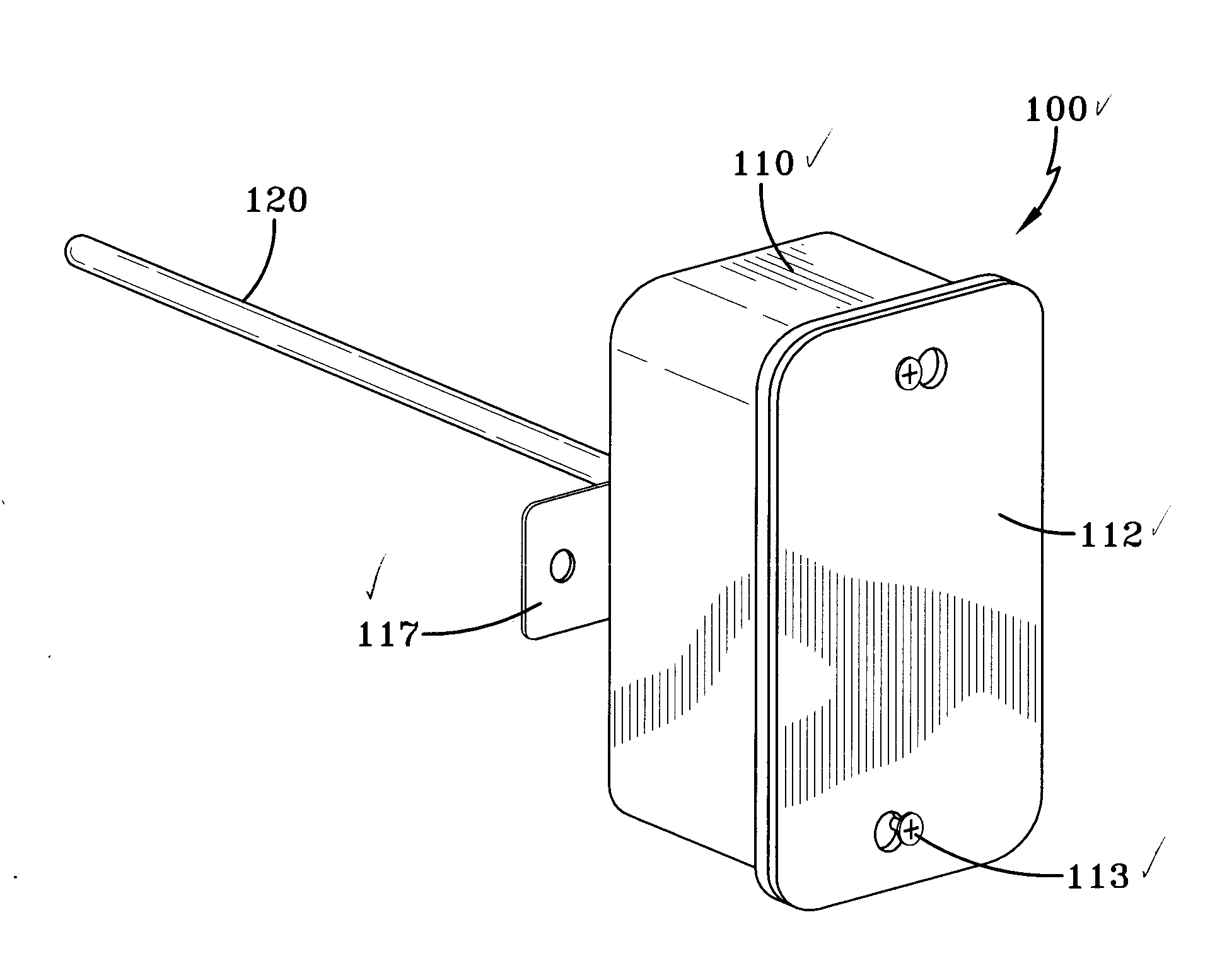
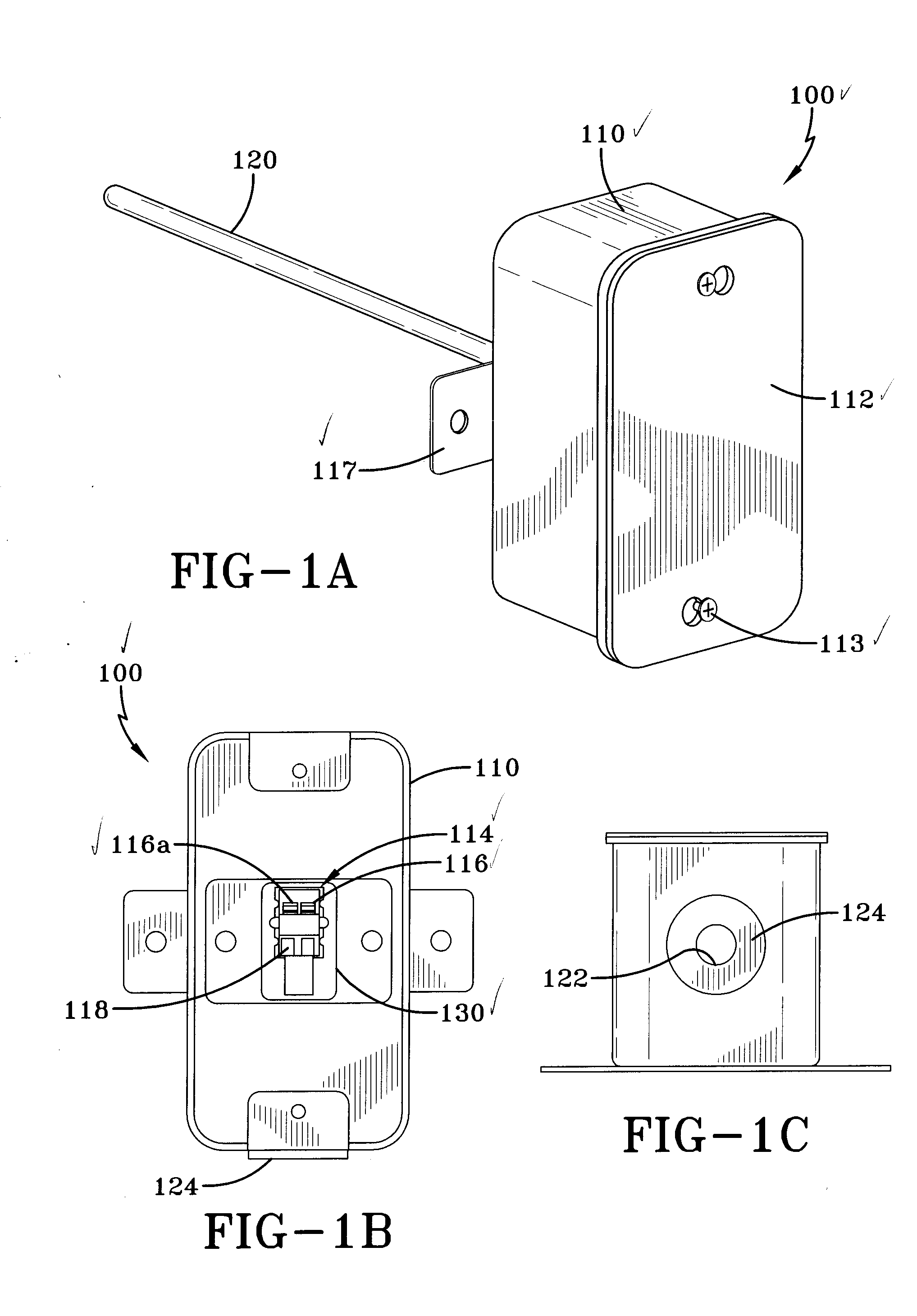
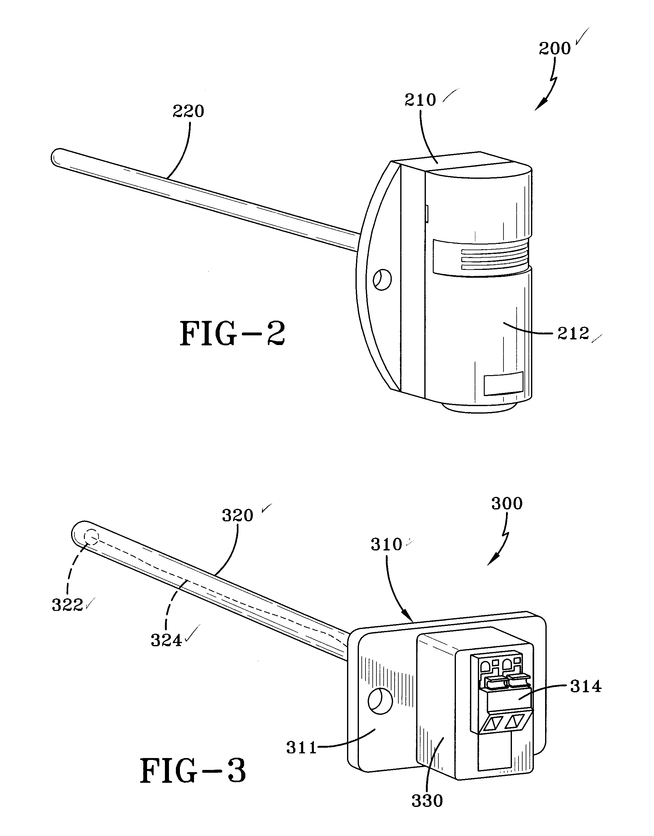
[0017]FIGS. 1-6 show various views of multiple embodiments of a probe apparatus according to the invention.

[0018]FIG. 1A illustrates an embodiment of a probe apparatus 100. The probe apparatus 100 includes a housing 110 and a sheath 120. The housing 110 includes a removable side 112. The removable side 112 is attached to the housing 110 by fasteners 113. The fasteners 113 that attach the removable side 112 to the housing include screws, bolts and nuts and the like. The fasteners, however, are not so limited and in other embodiments, may include latches, magnets or other fastening devices. The housing 110 further includes attachment portions 117, such as the flanges extending from housing 110, for attaching the probe apparatus to a structure (not shown), such as, but not limited to, a fluid duct, wall, joist, post, stud and the like (not shown).

[0019]The sheath 120 surrounds a sensor (not shown). The sensor may be a thermistor, thermocouple, a resistive temperature sensor, or other d...


PUM


Abstract

A temperature probe having a terminal attachment arrangement for securing and selectively releasing an electrical connection is disclosed. The temperature probe further includes a housing for sealing the temperature probe to a structure, such as a HVAC duct.

Description

CROSS REFERENCE TO RELATED APPLICATIONS[0001]This patent application claims the benefit of U.S. Provisional Patent Application Ser. No. 61 / 437,405 filed on Jan. 28, 2011, and entitled “THERMAL PROBE”, the disclosure of which is hereby incorporated by reference herein in its entirety and made part of the present U.S. utility patent application for all purposes.FIELD OF THE INVENTION[0002]The present invention relates generally to a probe apparatus. It relates more particularly to a thermal probe for HVAC applications having a releasable wire attachment device.BACKGROUND OF THE INVENTION[0003]Temperature sensors typically include a sensing element that provides a signal to an electrical circuit. The sensing element may be a resistive temperature detector, a thermocouple, or a thermistor, which changes electrical resistance based on temperature. As the electrical resistance of the sensing element changes, the electrical circuit can measure the electrical resistance and determine the co...

Claims


Application Information

Patent Timeline
IPC IPC(8): G05D23/22G01K7/02G05D23/24G01K7/16
CPCG01K1/14G01K2201/00F24F11/0012G01K7/22F24F2011/0082G01K7/16F24F11/008F24F11/30F24F2110/10F24F11/83F24F11/84F24F11/76F24F11/89F24F11/46
Inventor VAN DIJK, THOMAS J.POOL, KEVIN
Owner TASSSERON SENSORS
Why Eureka
Try Eureka