Electric brake apparatus

a technology of electric brakes and brake pads, which is applied in the direction of braking systems, braking components, transportation and packaging, etc., can solve the problems of reducing vehicle stability, unable to accurately calculate the thrust force value of electric brakes, etc., and achieve the effect of maintaining predetermined control accuracy

Active Publication Date: 2012-08-02
HITACHI ASTEMO LTD
View PDF13 Cites 33 Cited by
  • Summary
  • Abstract
  • Description
  • Claims
  • Application Information

AI Technical Summary

Benefits of technology

[0006]An object of the present invention is to provide an electric brake apparatus capable of maintaining predetermined control accuracy despite a change over time.

Problems solved by technology

According to the above-described conventional technique, although the electric brake apparatus can perform control without using any thrust force sensor, the electric brake apparatus may become unable to accurately calculate an estimated thrust force value due to a change in the mechanical portion over time.
If this state occurs at left wheel and right wheel sides, this may result in a reduction in the vehicle stability at the time of a brake operation.

Method used


Image

  • Electric brake apparatus
  • Electric brake apparatus
  • Electric brake apparatus

Examples


first embodiment

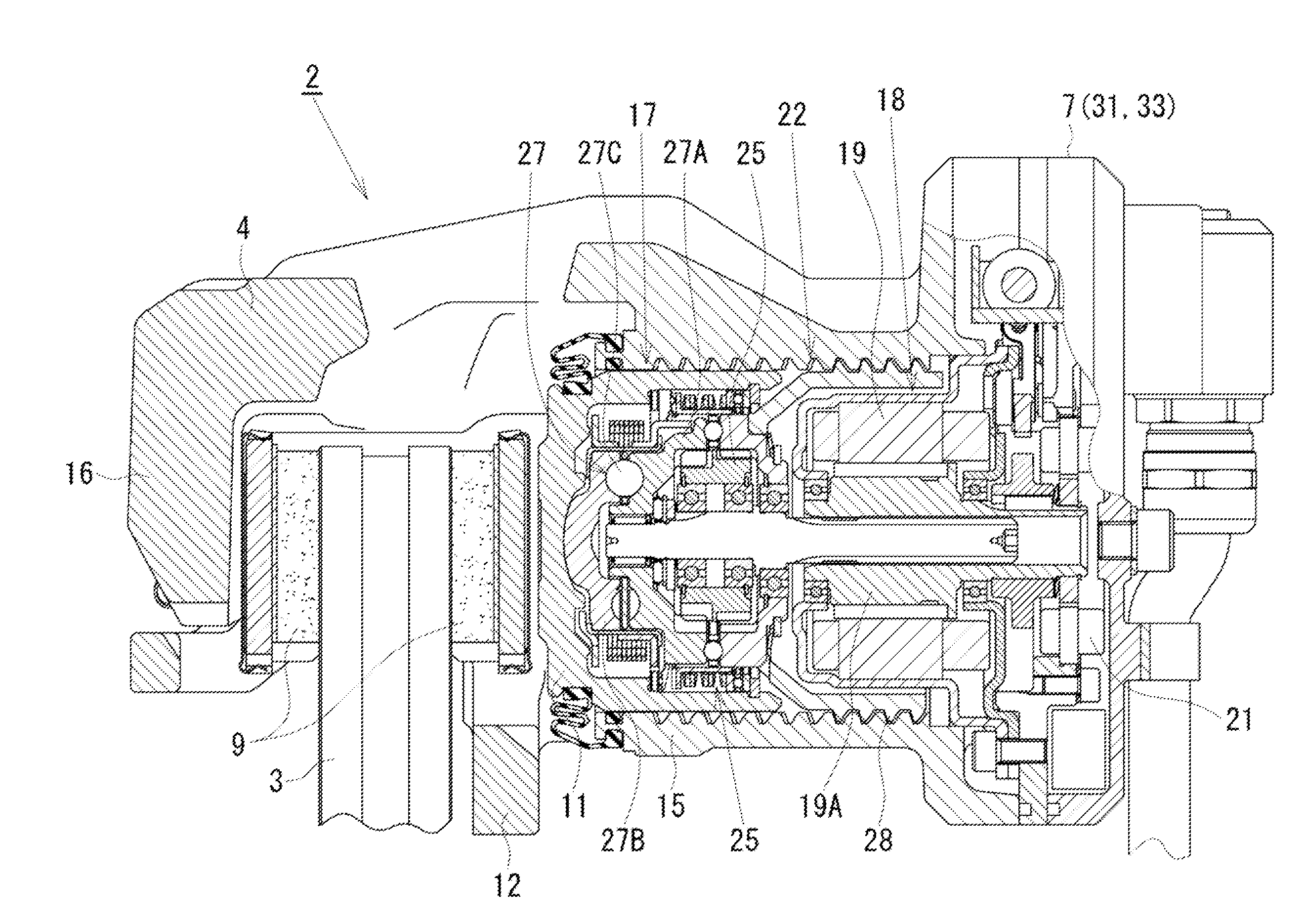
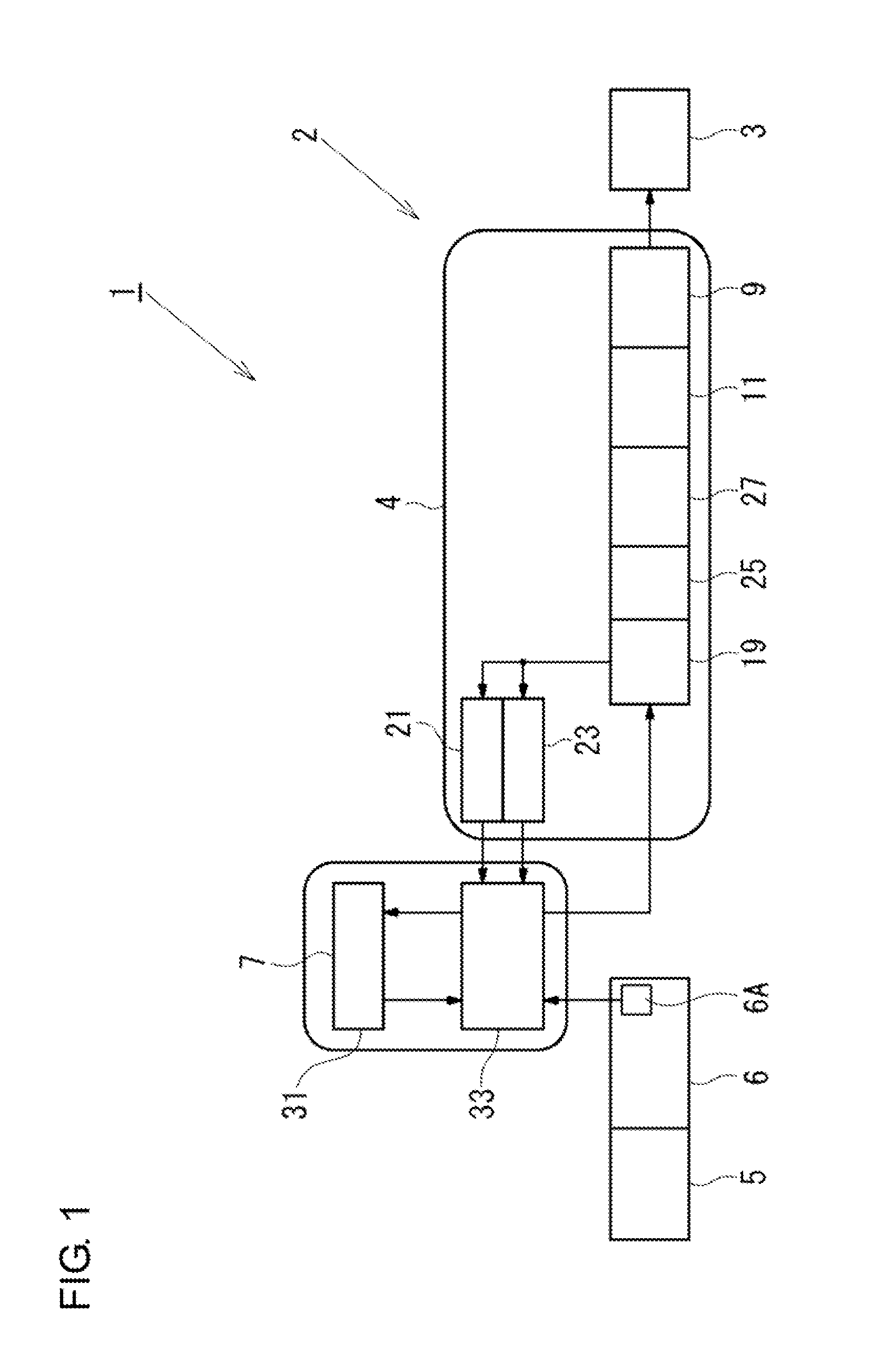
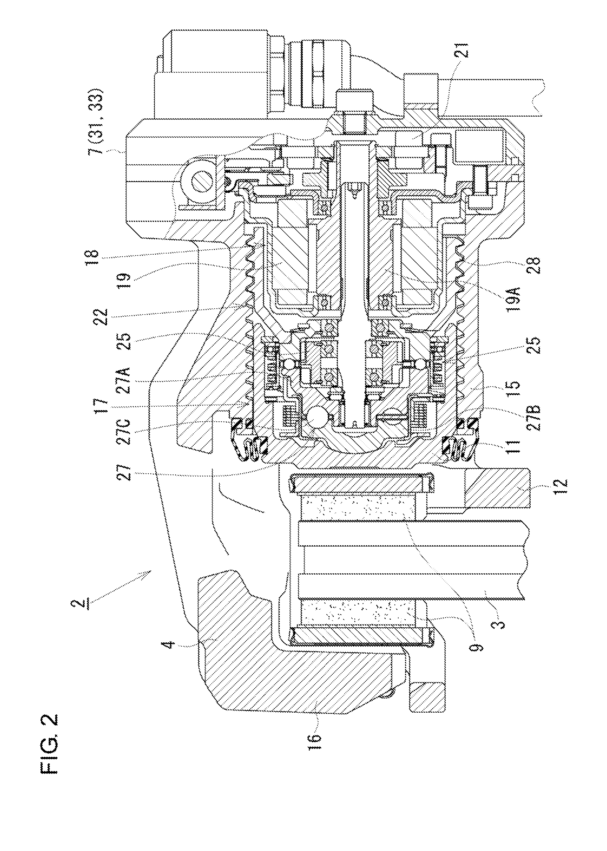
[0026]In the following, an electric brake apparatus according to a first embodiment of the present invention will be described with reference to the accompanying drawings. FIG. 1 is a block diagram illustrating an overall configuration of an electric brake apparatus according to the present embodiment. As illustrated in FIG. 1, the electric brake apparatus 1 according to the present embodiment includes electric calipers 2 (only one of them illustrated) respectively disposed at the front, rear, right, left wheels of an automobile which is one example of a vehicle, and a controller 7 (control unit) configured to supply a control signal to the electric calipers 2 based on input signals from various kinds of sensors configured to detect vehicle conditions such as a vehicle speed and a vehicle acceleration. The controller 7 receives operation information (for example, a stroke and an operation force) of a brake pedal 5, which is detected by an operation sensor 6A. The operation sensor 6A...

second embodiment

[0089]Next, a second embodiment will be described with reference to FIG. 18. A difference of the present embodiment from the first embodiment is that; in the present embodiment, the controller 7 directly converts a thrust force instruction into an electric current instruction As to control the electric motor 19, instead of converting a thrust force instruction into a rotational position instruction Xs. In the following, like components will be identified by the same reference numerals as those in the first embodiment, and only different features will be described in detail.

[0090]In the present embodiment, the controller 7 includes an ECU 33A and a RAM 31A illustrated in FIG. 18. In the ECU 33A, the thrust force instruction Fs issued from the pedal operation amount / thrust force instruction conversion unit 35 is directly converted into the electric current instruction As by a thrust force instruction / electric current instruction conversion unit 37A, and is transmitted to the electric ...


PUM


Abstract

The present invention provides an electric brake apparatus capable of maintaining predetermined control accuracy despite wear of a brake pad and other changes over time. The electric brake apparatus compares an estimated thrust force corresponding to a predetermined rotational position of an electric motor, which is calculated from an electric current/thrust force conversion function, with a reference thrust force based on a rotational position/thrust force table indicating a relationship between the rotational position of the electric motor and a thrust force of a piston to correct and update the electric current/thrust force conversion function, thereby maintaining predetermined control accuracy despite wear of the brake pad and other changes over time.

Description

BACKGROUND OF THE INVENTION[0001]1. Field of the Invention[0002]The present invention relates to an electric brake apparatus for use in braking of a vehicle.[0003]2. Related Art[0004]Electric brake apparatuses, which function to brake a vehicle with use of an electric motor as a driving source, calculate electric current that is contributive only to generation of a thrust force for a linear motion, i.e., thrust force contributive electric current by subtracting, for example, electric current ripples, and electric current corresponding to a resistance against a sliding motion including viscosity of grease at the mechanical portion actuated by the electric motor (viscosity / frictional torque component current) from electric current for driving the electric motor, and then estimate a thrust force by multiplying this thrust force contributive electric current by a function determined from the characteristics of the mechanical portion and the motor, such as an electric current / thrust forc...

Claims


Application Information

Patent Timeline
Patent Type & Authority Applications(United States)
IPC IPC(8): F16D65/14
CPCB60T13/741B60T17/221F16D65/18F16D65/567F16D2125/50F16D2066/005F16D2066/006F16D2121/24F16D2125/36F16D2066/003F16D66/00
Inventor GOTO, DAISUKEOIKAWA, HIROTAKAUSUI, TAKUYA
Owner HITACHI ASTEMO LTD
Why Eureka
Try Eureka