
Cogeneration apparatus

a technology of cogeneration apparatus and power generator, which is applied in the direction of lighting and heating apparatus, machines/engines, transportation and packaging, etc., can solve the problem of difficult to positively cool the power generator, and achieve the effect of efficient cooling the power generator

Active Publication Date: 2012-08-02
HONDA MOTOR CO LTD
View PDF10 Cites 1 Cited by
  • Summary
  • Abstract
  • Description
  • Claims
  • Application Information

AI Technical Summary

Benefits of technology

The present invention provides an improved cogeneration apparatus that can efficiently cool the power generator and prevent exhaust gas from flowing out of the engine. The apparatus includes an airtight chamber within the housing, an intake duct for introducing air from outside the housing, and an exhaust duct for discharging exhaust gas. The intake duct cools the interior of the airtight chamber, while the exhaust duct cools the power generator. The apparatus also includes a cover member to prevent the power generator from getting wet with waterdrops entering through the intake duct. The exhaust duct is constructed as a dual structure to improve space efficiency and reduce installation costs. The invention also includes a connection duct for interconnecting the external duct and the extension duct. The lower piece of the connection duct has a flange and concentric ribs to prevent condensed water from dripping down and to allow for the flows of the condensed water.

Problems solved by technology

However, with the cogeneration apparatus, which includes as its main components the engine, power generator and exhaust heat exchanger and which are installed indoors, it is necessary to install the engine in an airtight chamber in order to prevent exhaust gas from flowing out from the engine to the interior of the housing, and, besides, it is difficult to positively cool the power generator.

Method used


Image

  • Cogeneration apparatus
  • Cogeneration apparatus
  • Cogeneration apparatus

Examples


Embodiment Construction

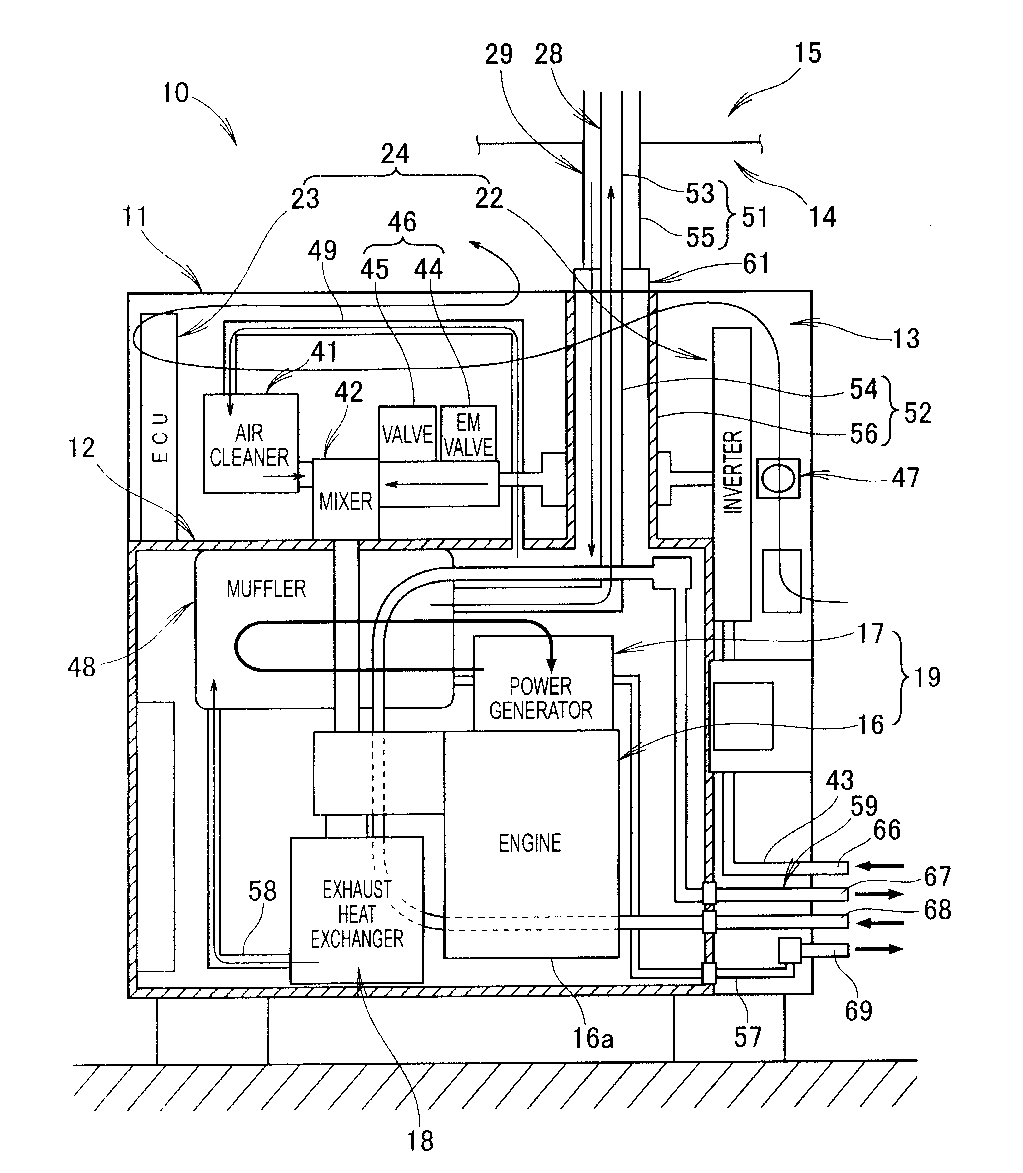
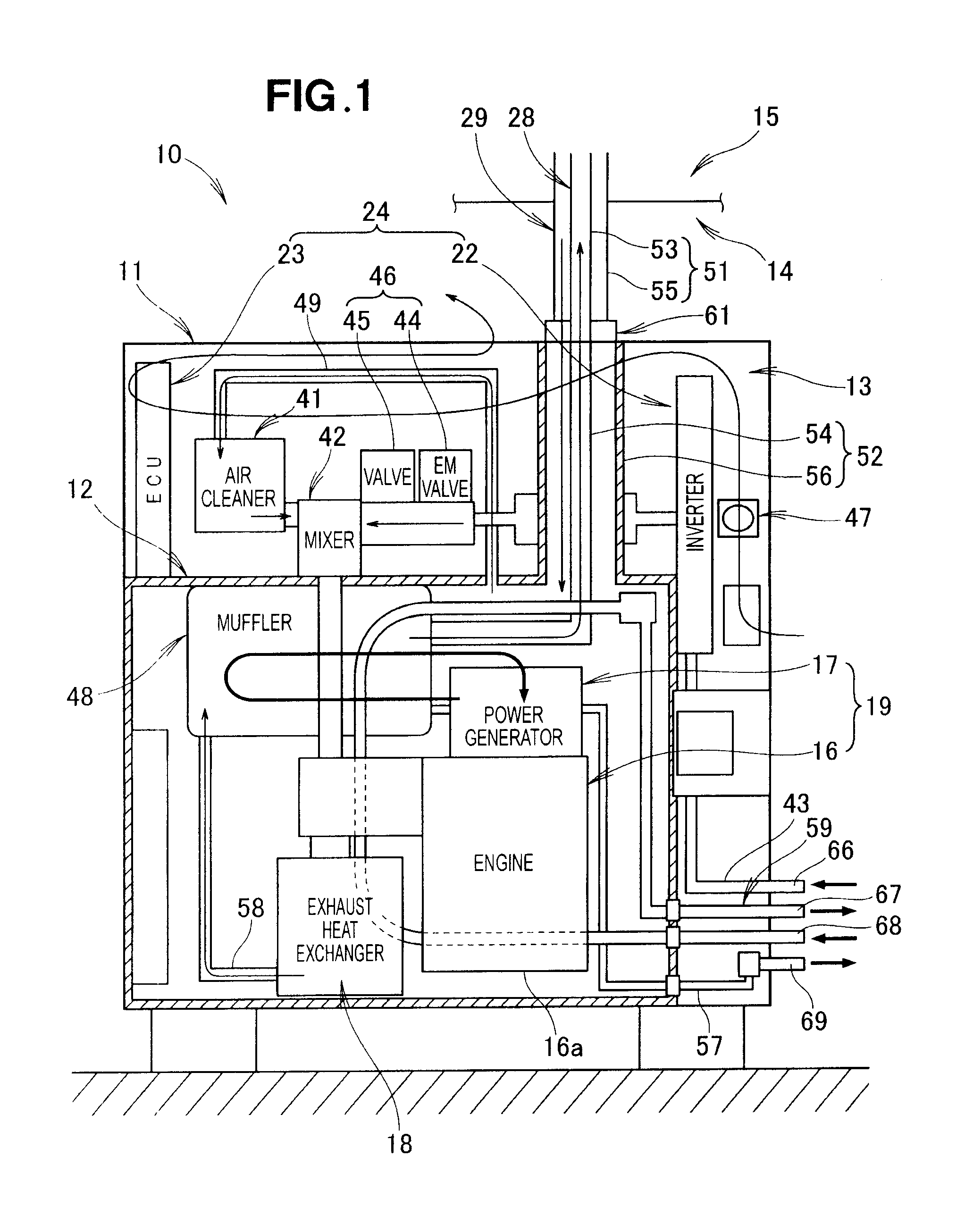
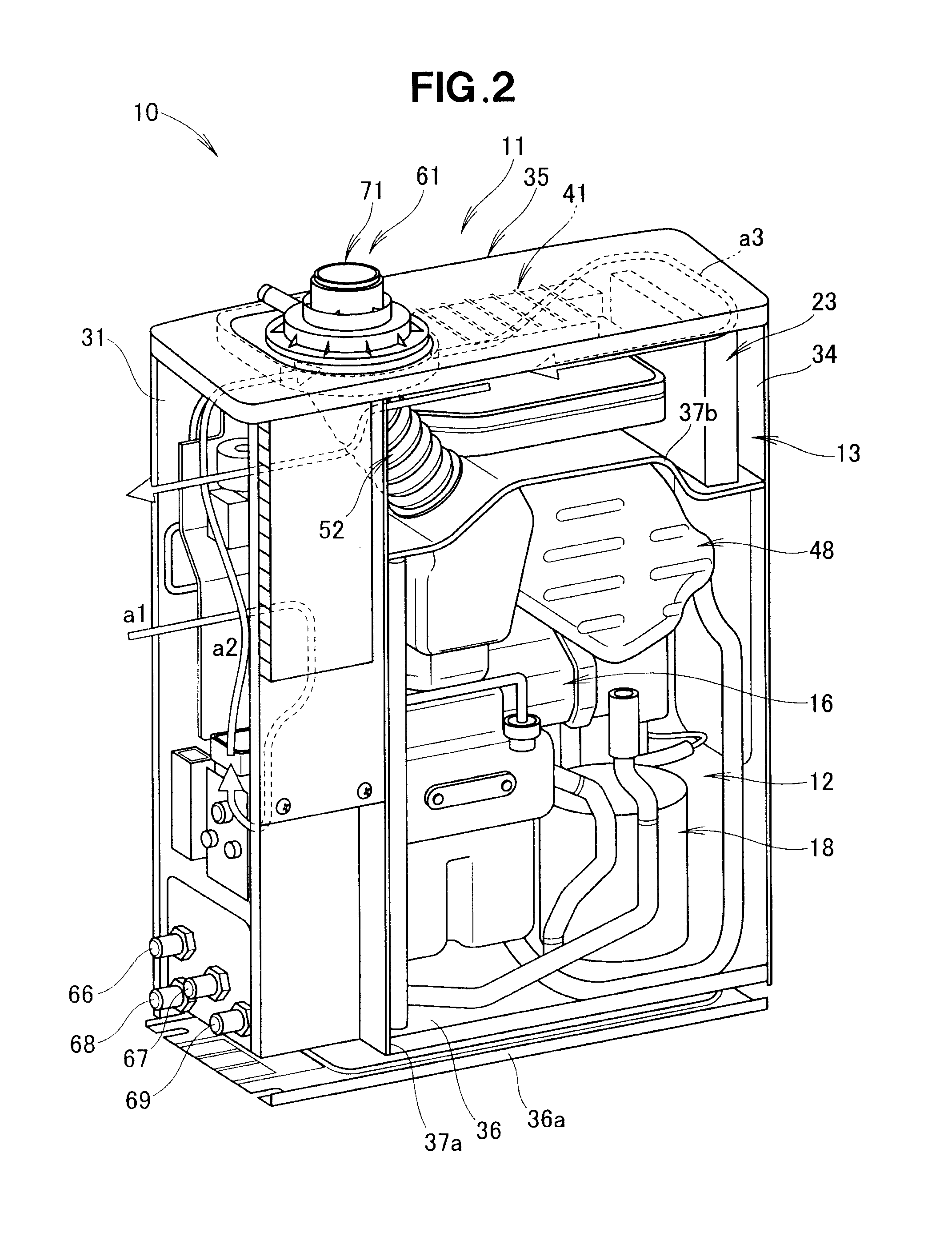
[0030]Reference is now made to FIGS. 1 to 3 which illustrate in block diagram and rear perspective views, an embodiment of a cogeneration apparatus according to the present invention. The “cogeneration” is also called “combined heat and power”, which is among new energy supply systems that take out power, heat and cold by use of exhaust heat of an internal combustion engine or external combustion engine and thereby achieve an enhanced total energy efficiency.

[0031]The embodiment of the cogeneration apparatus 10, which is suitably installable indoors 14, includes, as its main components: a power generator (starter-generator) 17 connectable to a commercial power source (not shown); an engine (internal combustion engine) 16 for driving the power generator 17; an exhaust heat exchanger 18 for heat-exchanging cooling water of the engine 16 with exhaust heat of the engine 16 to raise the temperature of the cooling water; an exhaust-heat-using hot-water supply / heating unit (not shown) that...


PUM


Abstract

A cogeneration apparatus for indoor installation includes: an airtight chamber provided within a housing, at least a power generator and an engine being accommodated within the airtight chamber; an intake duct connected to the airtight chamber for introducing air from outside the housing into the airtight chamber; and an exhaust duct connected to the engine for discharging exhaust gas of the engine. The air introduced through the intake duct cools the interior of the airtight chamber and is also sucked in to an air cleaner of the engine, and the exhaust gas of the engine is discharged directly to outside the airtight chamber through the exhaust duct.

Description

FIELD OF THE INVENTION[0001]This invention relates to a cogeneration apparatus which includes an engine, power generator and exhaust heat exchanger accommodated within a housing and an external duct (chimney) interconnecting the housing and outdoors, and which is suitable for indoor installation.BACKGROUND OF THE INVENTION[0002]Generally, the cogeneration apparatus include: an engine as a power source; a power generator drivable by the engine to generate electric power; a heat exchanger (i.e., exhaust heat exchanger) for exchanging heat from the engine; a soundproof housing accommodating the engine, power generator and exhaust heat exchanger; an air inlet or intake port provided in one side wall of the soundproof housing for introducing air into the soundproof housing; an exhaust outlet or discharge port provided in another side wall of the soundproof housing for discharging exhaust (gas) from the engine; and a ventilation fan for sucking in air from the air intake port. A motor sec...

Claims


Application Information

Patent Timeline
Patent Type & Authority Applications(United States)
IPC IPC(8): F02C6/18
CPCF23J2211/101Y02E20/14F23J13/025Y02T10/12
Inventor SASAKI, NOBUYUKIMATSUSHITA, KATSUTOSHIYURI, NOBUYUKIOKA, KOICHI
Owner HONDA MOTOR CO LTD
Learn More