Control circuit and data hold device using the control circuit
a control circuit and data hold technology, applied in the direction of generating/distributing signals, pulse techniques, instruments, etc., can solve the problems of higher power consumption, slowing down or increasing the power consumption of storage elements,
- Summary
- Abstract
- Description
- Claims
- Application Information
AI Technical Summary
Benefits of technology
Problems solved by technology
Method used
Image


Examples
first embodiment
The First Embodiment
[0186]Furthermore, in the embodiment, it takes the structure of the respectively combined inverter INV6 and path switch SW3, and inverter INV7 and path switch SW4 as the examples for illustration, but this is not the limitation of the structure of the present invention; it may also be as shown in FIG. 7 that the output state is set to be three-state inverters INV6′ and INV7′ at a high impedance according to the control signal E1 so as to omit the path switches SW3 and SW4. Under this condition, the structure of the inverter INV6′ (the same as the inverter INV7′) is shown in FIG. 8.
[0187]FIG. 8 is a circuit diagram showing a structural example of the three-state inverter INV6′(the same as the inverter INV7′) having potential shifting function.
[0188]As shown in FIG. 8, the three-state inverter INV6′(INV7′) having potential shifting function may be easily realized through adding multiple changes to the above inverter INV6 (INV7). More specifically, based on the stru...
fourth embodiment
The Fourth Embodiment
[0220]Then, the fourth embodiment of the data hold device of the present invention is illustrated in detail while referring to FIG. 18. FIG. 18 is a circuit diagram which shows the fourth embodiment of the data hold device of the present invention.
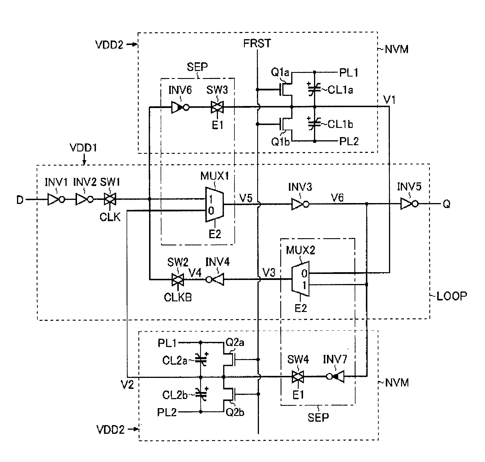
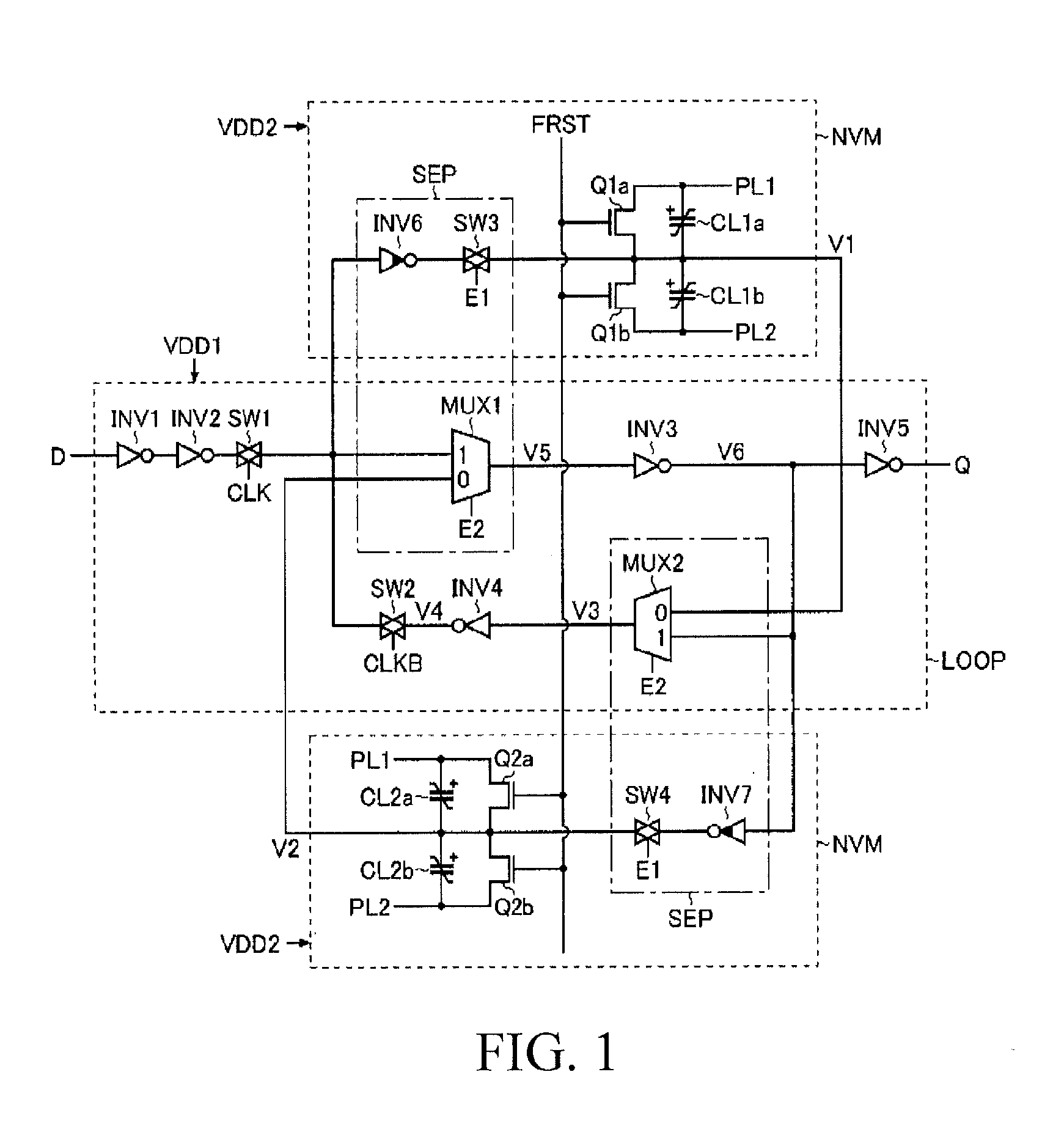
[0221]The data hold device described in FIG. 14 is a latch circuit including the inverters INV1-INV7, the path switches SW1-SW4, the multiplexers MUX1-MUX4, the demultiplexers DeMUX1, DeMUX2, the N-channel field effect transistors Q11a-Q1ma, Q11b-Q1mb, Q21a-Q2ma, Q21b-Q2mb, and the ferroelectric elements (ferroelectric capacitors) CL11a-CL1ma, CL11b-CL1mb, CL21a-CL2ma, CL21b-CL2mb.
[0222]An input end of the inverter INV1 is connected to an applying end of a data signal (D). An output end of the inverter INV1 is connected to an input end of the inverter INV2. An output end of the inverter INV2 is connected to a first input end (1) of the multiplexer MUX1 through the path switch SW1. An output end of the multiplexer MUX1...
fifth embodiment
The Fifth Embodiment
[0303]Then it describes the fifth embodiment of the data hold device of the present invention in details referring to FIG. 26. FIG. 26 is a circuit diagram of the fifth embodiment of data hold device of the present invention. And so far in the description, it exemplifies the structure offering different supply voltages to the loop structure portion LOOP and the non-volatile storage portion NVM respectively, however, the present invention is not restricted thereof, it also can offer the same supply voltage to the loop structure portion LOOP and the non-volatile storage portion NVM. Hence, in the following fifth embodiment, it will not mention whether the supply voltage offered to the loop structure portion LOOP and the non-volatile storage portion NVM is consistent / inconsistent, but to focus on explaining portions of the structure different from the previous disclosure.
[0304]As shown in FIG. 26, the data hold device of the embodiment includes the loop structure po...
PUM
 Abstract
Description
Claims
Application Information
 - R&D
- Intellectual Property
- Life Sciences
- Materials
- Tech Scout
- Unparalleled Data Quality
- Higher Quality Content
- 60% Fewer Hallucinations
Browse by: Latest US Patents, China's latest patents, Technical Efficacy Thesaurus, Application Domain, Technology Topic, Popular Technical Reports.
© 2025 PatSnap. All rights reserved.Legal|Privacy policy|Modern Slavery Act Transparency Statement|Sitemap|About US| Contact US: help@patsnap.com