
Combustion apparatus

Active Publication Date: 2012-08-02
SIEMENS ENERGY GLOBAL GMBH & CO KG
View PDF6 Cites 16 Cited by
  • Summary
  • Abstract
  • Description
  • Claims
  • Application Information

AI Technical Summary

Benefits of technology

[0006]It is a common problem that, due to the high temperatures generated inside such combustors, various component parts of the combustors run the risk of overheating, which can seriously damage the combustor, or at least impair its performance. Also NOx emissions—NOx stands for oxides of nitrogen as the chemical compounds NO and NO2 —are a major concern. It is an aim of the invention to provide a combustion apparatus which reduces the risk of such overheating and is directed to create only low emissions at a wide range of operation.
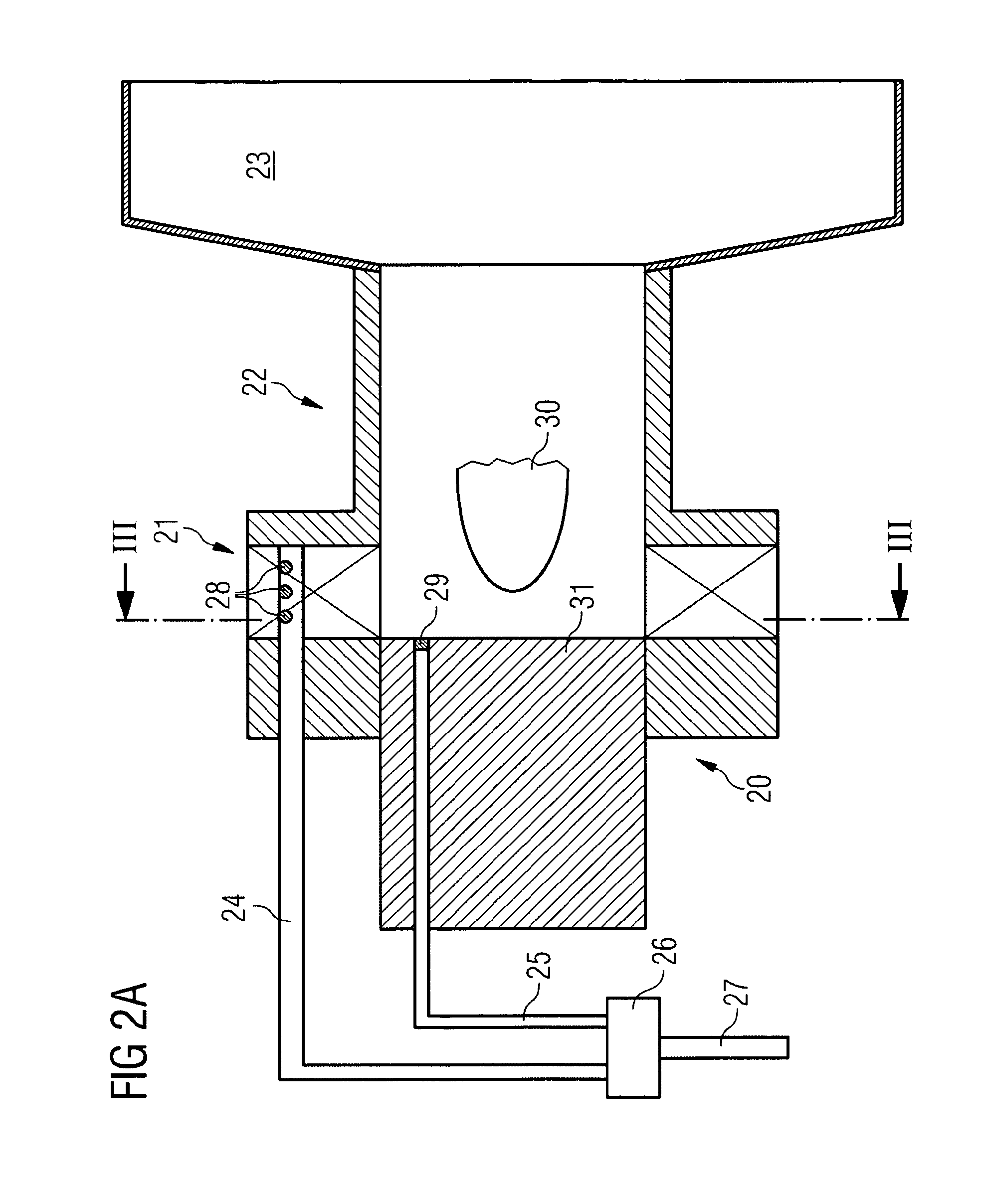
[0012]a temperature sensor located in the apparatus such as to be able to convey temperature information relating to a part of the apparatus which is to be protected against overheating;
[0016]The inventive concept is specifically advantageous because it can be avoided to operate the apparatus in a unstable condition or in a condition which results in a too high temperature impacts on surfaces within the combustion volume or on the burner. By also considering the time information, it is possible to vary the fuel supplies at discrete points of time and keep the fuel supply unvaried in between. Besides this allows to vary the fuel supplies frequently in such a way, that the point of operation will stay close to but not in a specific range of operation, e.g. close to operational points in which higher pressure dynamics occur (with the advantage that less NOx will be produced) or in which high temperatures occur (with the advantage that the apparatus will provide a stable combustion). On the other hand, the evaluation of the further information which is indicative for a progress over time for the signal may guarantee that the variation of the fuel supplies does not occur in a too frequent manner allowing a steady-going mode of operation without changing the valve settings for the fuel supplies continuously and avoiding oscillations for the valve settings.
[0019]In a further embodiment and in a first mode of operation the control arrangement may further be configured such as to vary the fuel supplies at points in time defined by the time information in such a way that the temperature of said part to be protected is regulated so that the difference of the predetermined maximum temperature limit and the temperature of said part represented by the temperature information does not exceed a predefined temperature threshold. This may avoid overheating of parts.

Problems solved by technology

It is a common problem that, due to the high temperatures generated inside such combustors, various component parts of the combustors run the risk of overheating, which can seriously damage the combustor, or at least impair its performance.

Method used


Image

  • Combustion apparatus
  • Combustion apparatus
  • Combustion apparatus

Examples


first embodiment

[0065]In a first embodiment, the gas turbine will be operated with high NOx reduction by running close to region B that represents operating points with high pressure fluctuation. This embodiment is explained by referencing to FIG. 6A.

[0066]According to FIG. 6, the split between pilot fuel supplied to the pilot-fuel nozzle 29 and main fuel supplied to the main-fuel nozzles 28 follows the curve 60. The curve 60 follows a pre-defined fuel split map within an area of 61 for low load and an area 63 of high loads. Within the area 62 of medium loads FIG. 6 shows an area in which the curve 60 would follow the dashed line if the pre-defined fuel split map would be followed. In contrast to that the actual curve, which is a result of the inventive concept, is shown as a solid line in the areas 61, 62, 63 and “corrects” the fuel split so that none of the regions A or B will be a permanent point of operation.

[0067]For very low loads a high value of pilot fuel is provided to the burner. This fue...

third embodiment

[0086]In a third embodiment, the gas turbine will be operated with increased engine reliability by running close to region A that represents operating points with high temperatures on specific surfaces of the burner 20 or the combustion chamber. Especially if the pressure sensor or transducer signal fails and / or the gas turbine engine is running at a given site with predominant combustion dynamics problems, then running close to region A may be an option, to run the gas turbine engine most reliable. This embodiment is explained by referencing to FIG. 6B.

[0087]According to this second example, it is assumed that the fuel supply follows the main / pilot flow split map and at some point the load rises such as to start to encroach on area A (point 72). Under these circumstances the temperature information parameter will exceed the allowed maximum, the predetermined maximum temperature limit. As a result a specific active pilot control is started and the split is decremented to an assumed ...


PUM


Abstract

A combustion apparatus includes a fuel supply line for providing an overall fuel supply to the apparatus; a burner including multiple fuel supply lines, the supply of fuel in the fuel supply lines to the burner corresponding to the overall fuel supply in the fuel supply line to the apparatus, and a combustion volume associated with the at least one burner. A temperature sensor measures a temperature of a part of the apparatus to be protected against overheating. A pressure sensor measures pressure within the combustion volume. A control arrangement varies the fuel supplies to the burner based on the measured temperature and pressure and on an information indicative for a progress over time for a signal for a time span. The arrangement maintains the temperature of part to be protected and the pressure variations within the combustion volume below predetermined limits, while maintaining constant fuel supply to the apparatus.

Description

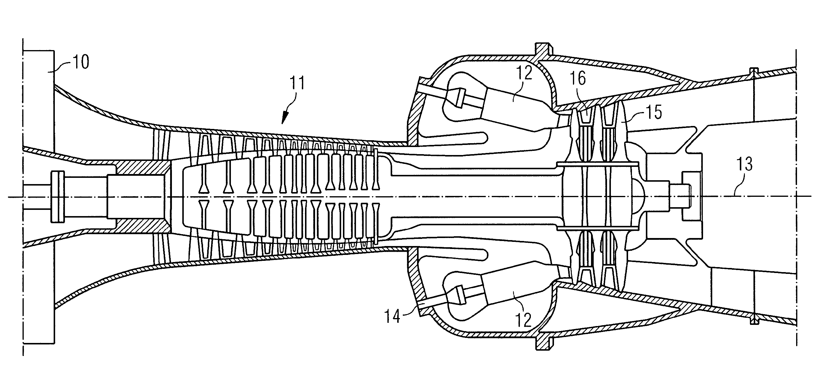
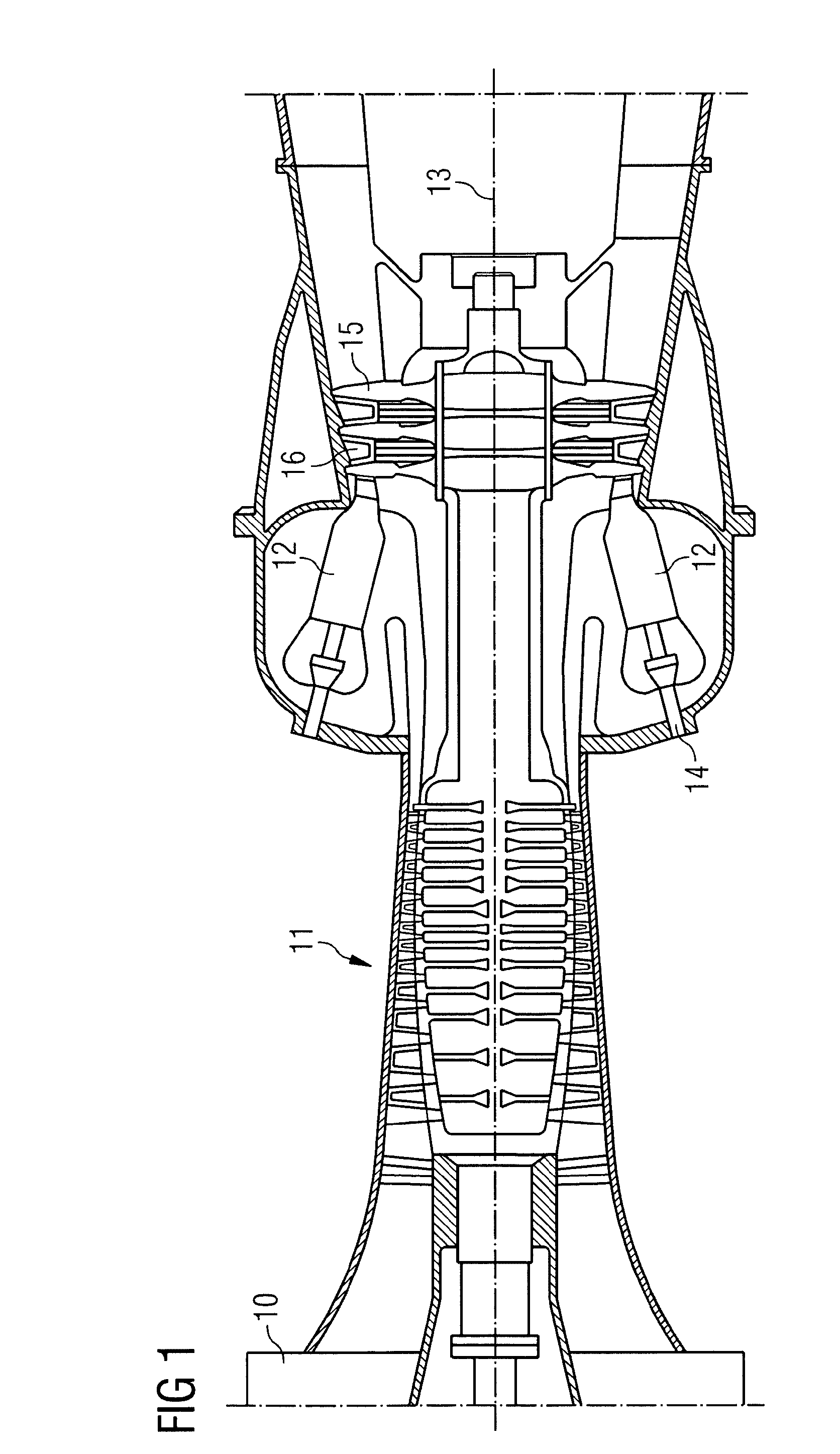
CROSS REFERENCE TO RELATED APPLICATIONS[0001]This application is the US National Stage of International Application No. PCT / EP2009 / 007299, filed Oct. 9, 2009 and claims the benefit thereof. All of the applications are incorporated by reference herein in their entirety.FIELD OF INVENTION[0002]The invention relates to a combustion apparatus and to a combustion apparatus constituted in particular by a gas turbine. Combustion apparatus is employed in a number of different environments, including gas turbines, furnaces and boilers.BACKGROUND OF INVENTION[0003]An example of a typical gas-turbine arrangement is shown in an abstract way in FIG. 1. The gas turbine comprises an air inlet 10 at one end followed by a compressor stage 11 in which incoming air is compressed for application to one or more combustors 12, which are distributed circumferentially around the turbine axis 13. Fuel is introduced into the combustors at 14 and is there mixed with a part of the compressed air leaving the co...

Claims


Application Information

Patent Timeline
IPC IPC(8): F23D5/12
CPCF02C9/28F05D2270/082F23C2900/07001F23D2900/14021F23N1/002F23N5/102F05D2270/303F23N5/242F23N2037/02F23R3/286F23R3/343F23R2900/00013F05D2270/112F23N5/16F23N2237/02
Inventor BULAT, GHENADIEMCMILLAN, ROBIN
Owner SIEMENS ENERGY GLOBAL GMBH & CO KG
Learn More