
Delivery methods for a biological pacemaker minimizing source-sink mismatch

a delivery method and source-sink technology, applied in the direction of catheters, peptide/protein ingredients, infusion needles, etc., can solve the problems of pacing dysfunction, limited lifetime, and certain technical limitations of implantable pacemakers

Inactive Publication Date: 2012-08-02
MEDTRONIC INC
View PDF6 Cites 5 Cited by
  • Summary
  • Abstract
  • Description
  • Claims
  • Application Information

AI Technical Summary

Benefits of technology

[0032]For any method disclosed herein that includes discrete steps, the steps may be conducted in any feasible order. And, as appropriate, any combination of two or more steps may be conducted simultaneously.

Problems solved by technology

While effectively improving the lives of many patients, such implantable pacemakers have certain technical limitations.
For example, implantable pacemakers rely on a self-contained power source such as a battery and consequently have a limited lifetime before the power source is in need of replacement.
This is particularly problematic in individuals who develop pacing dysfunction at a younger age.
In addition, implantable pacemaker batteries are large and are usually the bulkiest pacemaker component.
Also, implantable pacemakers have very limited or no capacity for directly responding to the body's endogenous signaling the way the SA node responds to such signaling, i.e. by a modulation of the heart rate relative to the physiological and emotional state (e.g. sleep, rest, stress, exercise).
Electronic pacemakers are also unable to mimic normal respiratory and autonomic tone mediated beat-to-beat variability in heart rate (heart rate variability), which are hypothesized to have impact on overall body homeostasis.
However, studies have yet to demonstrate the establishment of a biological pacemaker with long term stability.
With source-sink mismatch, if the tissue load on the regions driving the excitation (i.e. pacemaker region) is large relative to pacemaker's size, the pacemaker is unable to drive the tissue in a stable and reproducible manner.

Method used


Image

  • Delivery methods for a biological pacemaker minimizing source-sink mismatch
  • Delivery methods for a biological pacemaker minimizing source-sink mismatch
  • Delivery methods for a biological pacemaker minimizing source-sink mismatch

Examples


example 1

Dispersal of Gene Expression Following Cardiac Injection

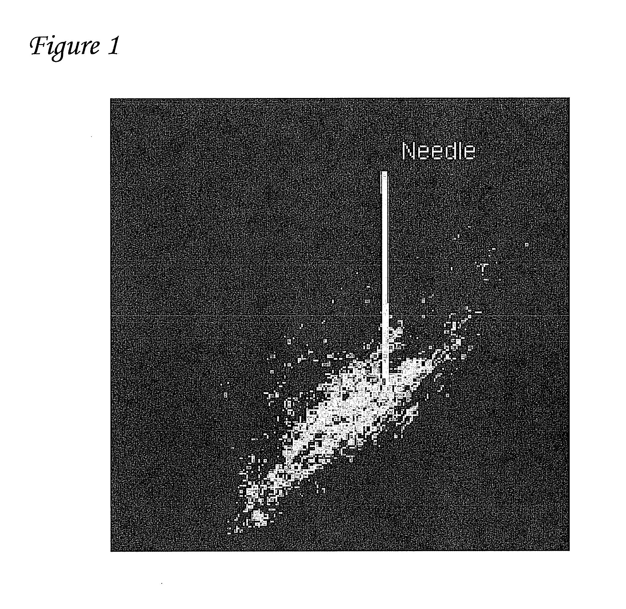
[0077]A single injection of ˜100 μ1 biologic volume of gene constructs expressing green fluorescent protein (GFP) or luciferase were injected into the left ventricle of pigs. Gene expression and dispersion of gene expression were monitored by fluorescent microscopy of histological samples. A representative sample is shown in FIG. 1. The white bar in FIG. 1 depicts the needle and is 10 millimeters (mm) long. As shown in FIG. 1, it was found that the gene disperses over a distance of ˜10 mm.

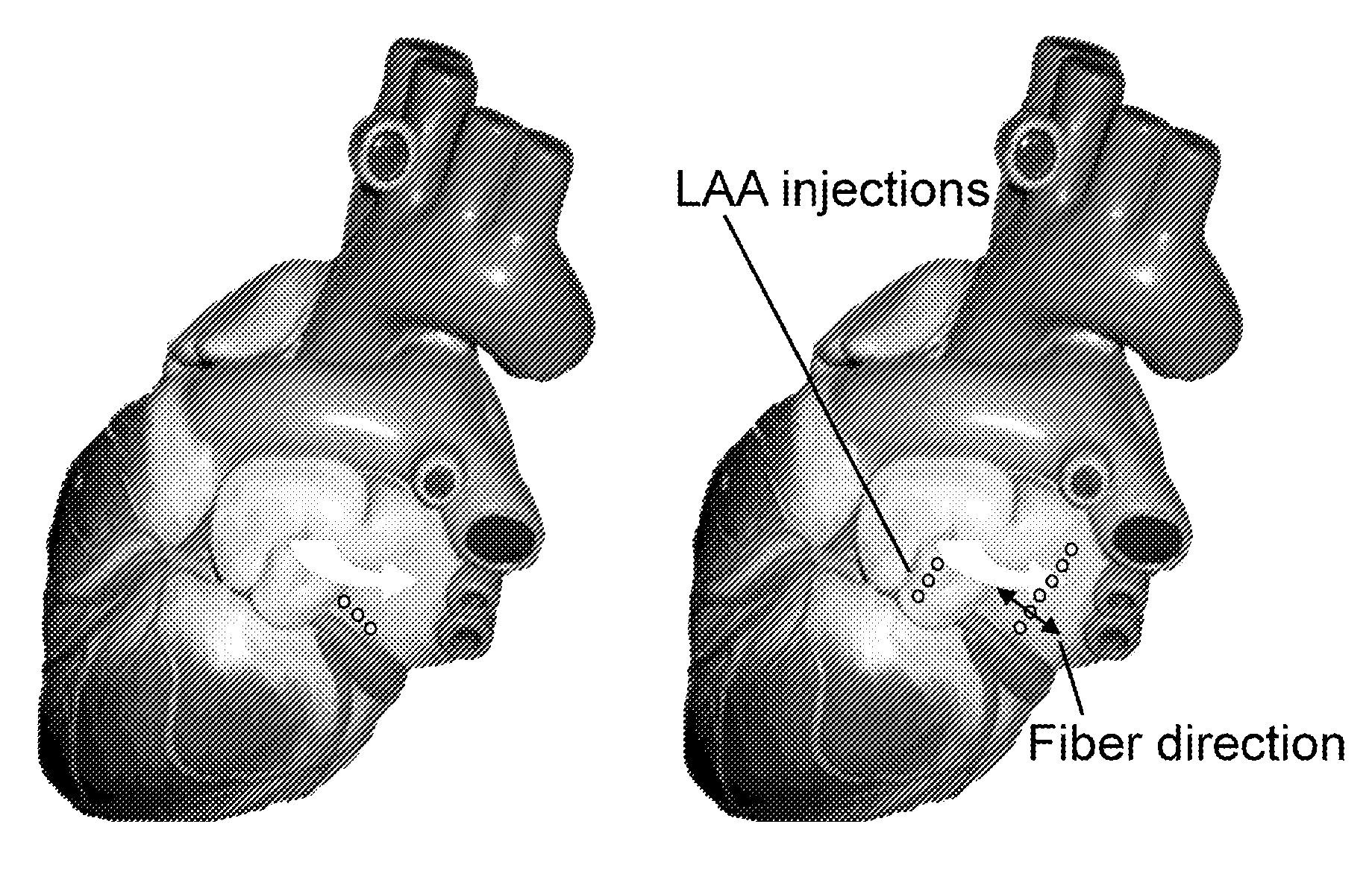
[0078]From these results it was determined that injections performed with a distance of about 2-5 mm between injections should be used to obtain optimal biopacemaker function. The asymmetric distribution of expression is likely because biologic solutions tend to disperse along the fiber direction. This information is critical and is taken into account during the biological injections. The transfected region that results from linear injections ...

example 2

Delivery of Biological Pacemaker Addressing Source-Sink Mismatch

[0079]Several efforts have been undertaken to create an artificial site in the heart that can mimic the pacemaking function of the SA nod. However, none of these studies have been able to demonstrate a stable biological pacemaker. See, for example, Qu et al., 2003, Circulation; 107(8):1106-9; Bucchi et al., 2006, Circulation; 114(10):992-9; Tse et al., 2006, Circulation; 114(10):1000-11; and Kashiwakura et al., Circulation; 114(16):1682-6. This variation in data and biopacemaking activity may be because these investigators overlooked something critical in the design of the biological pacemaker—the source-sink mismatch. With source-sink mismatch, if the tissue load on the regions driving the excitation (i.e. pacemaker region) is large relative to pacemaker's size, the pacemaker is unable to drive the tissue in a stable and reproducible manner. And, to achieve reliable excitation of the load tissue and produce stable pace...

example 3

Endocardial Delivery

[0085]Example 2 used an epicardial approach in which the access to the animal's heart was obtained by performing a thoracotomy. However, the same strategy can be implemented using an endocardial approach. With such an endocardial approach, an image guidance system may be used. When an image guidance system is used, each injection may be marked on the screen. Subsequent injections are to be placed about 2 mm to about 5 mm adjacent to preceding injections, in a linear pattern perpendicular to the fibers of heart tissue.

[0086]A needle catheter system that performs a linear injection endocardially may be used for the delivery of a biopacemaker gene. Such a needle catheter system may be a multi-needle catheter system. A tangentially approach in which needle is inserted tangential to the myocardium may also be used.

[0087]In such implementations, multiple electrodes along the length of the needle may be used to ensure that it is within the myocardium during injections. ...


PUM

PropertyMeasurementUnit
biologic volumeaaaaaaaaaa
angleaaaaaaaaaa
angleaaaaaaaaaa

Abstract

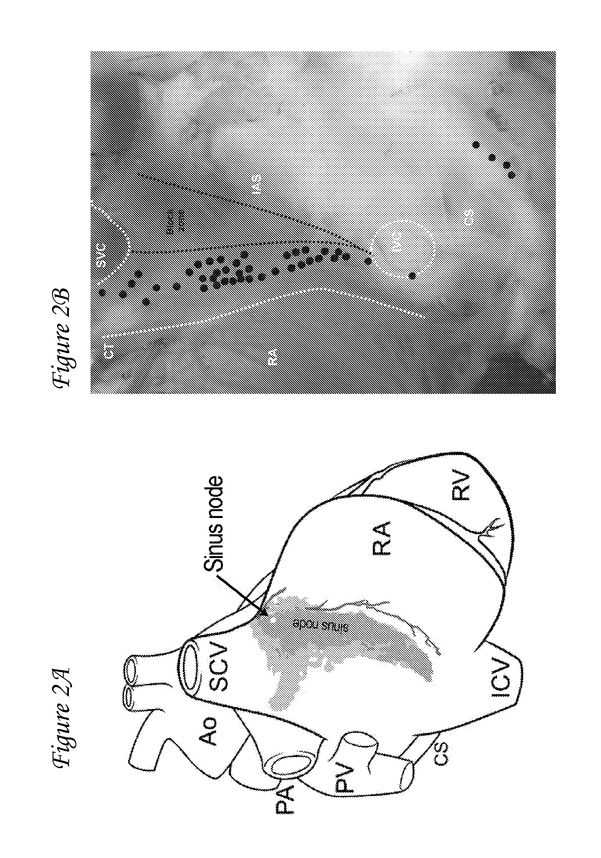
The present invention includes methods, systems, devices, and apparatus relating to minimizing source-sink mismatch associated with the application of a biological pacemaker in cardiac tissue. Stable and robust pacemaker activity is achieved by the application of the biological pacemaker at more than one site, in a linear pattern.

Description

CONTINUING APPLICATION DATA[0001]This application claims the benefit of U.S. Provisional Application Ser. No. 61 / 437,941, filed Jan. 31, 2011, which is incorporated by reference herein.BACKGROUND[0002]Cardiac contraction in a healthy human heart is initiated by spontaneous excitation of the sinoatrial (“SA”) node, which is located in the right atrium. The electric impulse generated by the SA node travels to the atrioventricular (“AV”) node where it is transmitted to the brindle of His and to the Purkinje network. The fibers in the Purkinje network branch out in many directions to facilitate coordinated contraction of the left and right ventricles, thus providing natural pacing. In some disease states, the heart loses some of its natural capacity to pace properly. Such dysfunction is commonly treated by implanting a pacemaking device that generates an electronic pulse.[0003]While effectively improving the lives of many patients, such implantable pacemakers have certain technical limi...

Claims


Application Information

Patent Timeline
Patent Type & Authority Applications(United States)
IPC IPC(8): A61M25/06A61M5/32A61M31/00
CPCA61M25/0084A61K38/00A61M2025/0089
Inventor SHARMA, VINOD
Owner MEDTRONIC INC
Learn More