
Solenoid valve for brake systems

Inactive Publication Date: 2012-08-09
HL MANDO CORP
View PDF3 Cites 6 Cited by
  • Summary
  • Abstract
  • Description
  • Claims
  • Application Information

AI Technical Summary

Benefits of technology

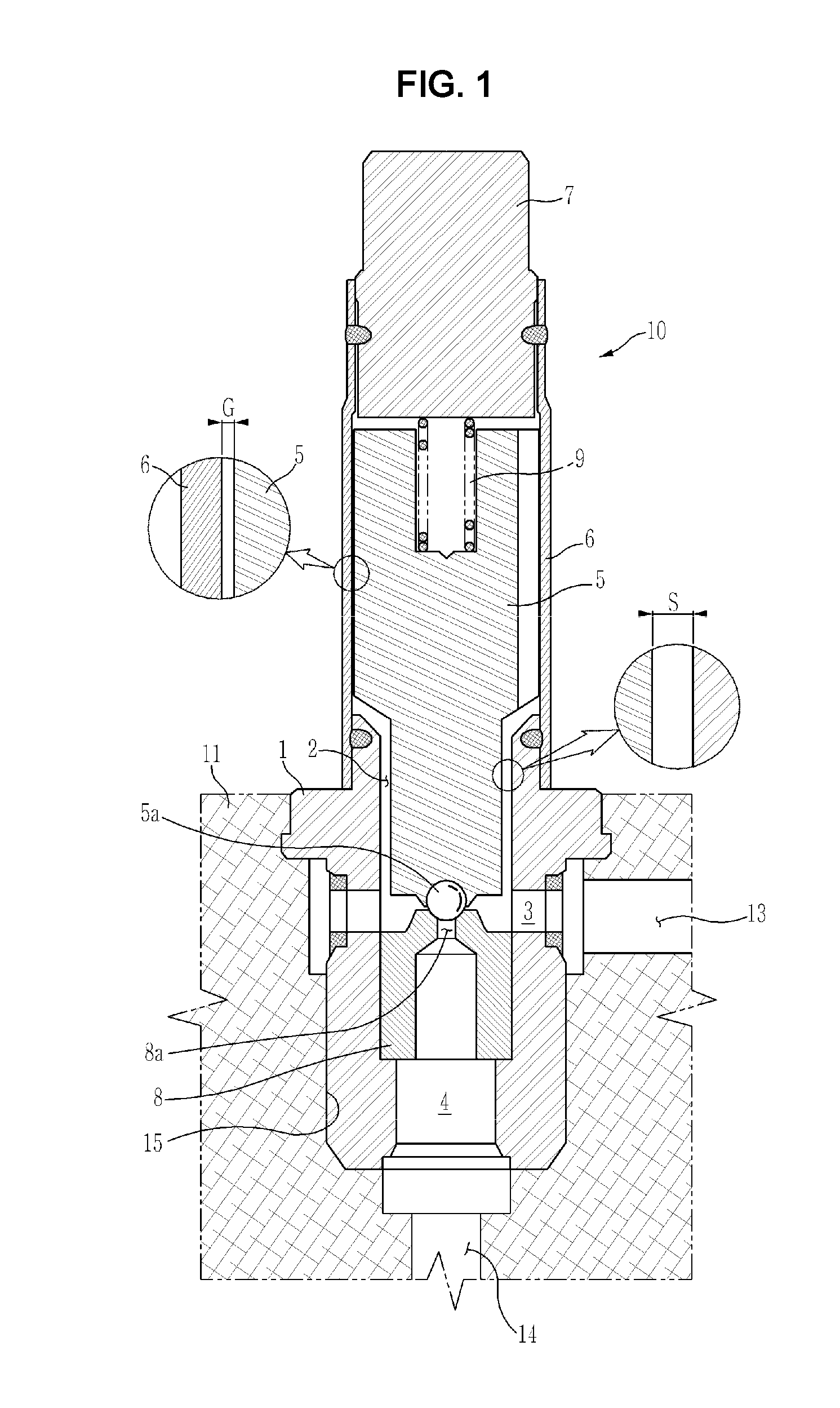
[0020]Therefore, it is an aspect of the present invention to provide a solenoid valve for brake systems which reduces a gap between an armature and a sheet housi

Problems solved by technology

Here, if braking force which is greater than static frictional force between a road surface and a tire is applied, slippage of the tire on the road surface occurs.

Method used


Image

  • Solenoid valve for brake systems
  • Solenoid valve for brake systems
  • Solenoid valve for brake systems

Examples


Embodiment Construction

[0034]Reference will now be made in detail to the embodiments of the present invention, examples of which are illustrated in the accompanying drawings, wherein like reference numerals refer to like elements throughout. The terms used in the following description are terms defined taking into consideration the functions obtained in accordance with the embodiments, and the definitions of these terms should be determined based on the whole content of this specification. The configurations disclosed in the embodiments and the drawings of the present invention are only exemplary and do not include all of the technical spirit of the invention, and thus it will be appreciated that the embodiments may be variously modified and changed.

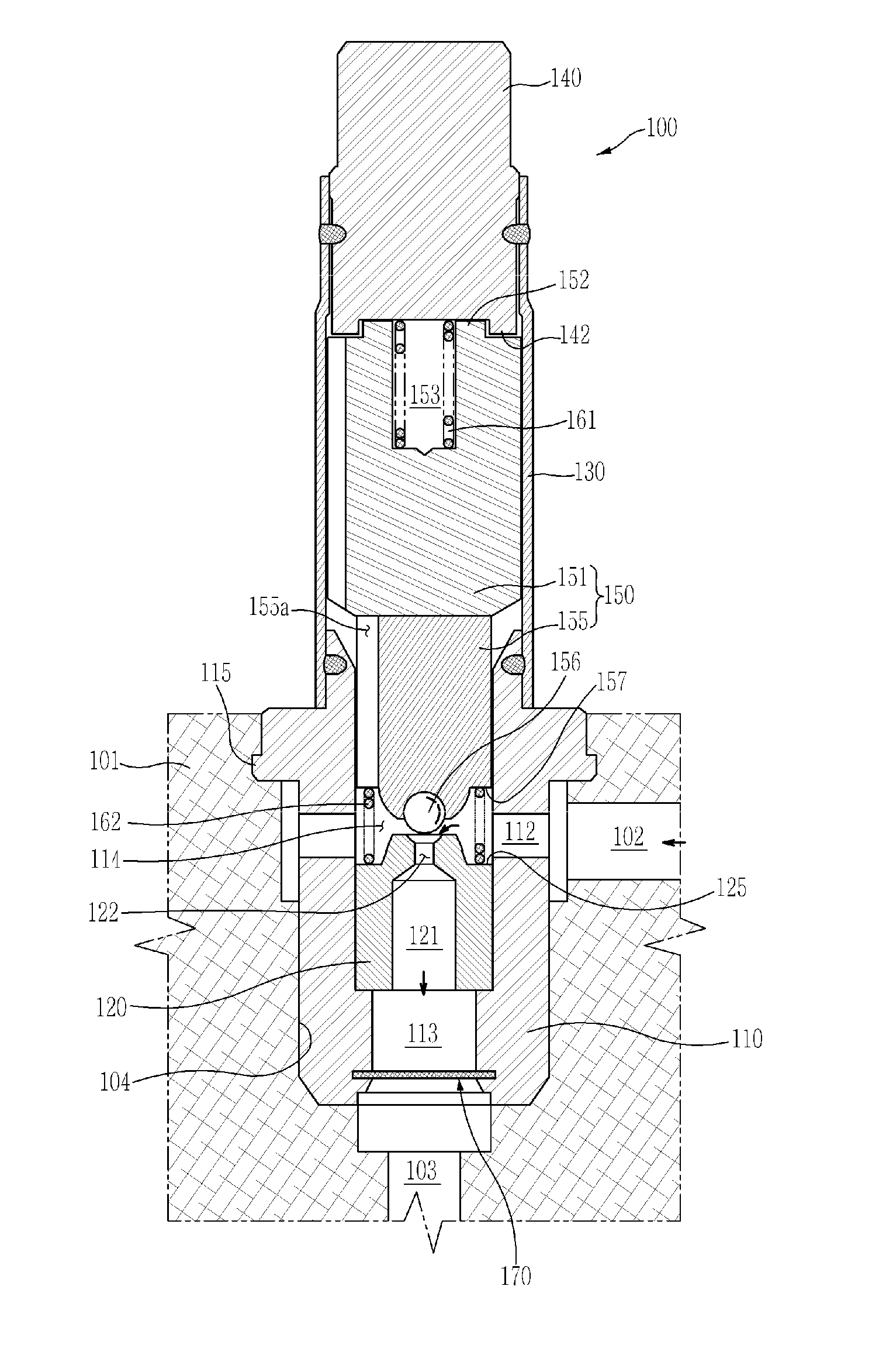
[0035]FIG. 3 is a longitudinal-sectional view illustrating a solenoid valve for brake systems in accordance with one embodiment of the present invention.

[0036]With reference to FIG. 3, a solenoid valve 100 for brake systems in accordance with this embodiment i...


PUM


Abstract

Disclosed herein is a solenoid valve for brake systems which improves an assembly structure of components constituting the valve to enhance durability and control performance of the valve. The solenoid valve includes a sheet housing, a valve sheet, a sleeve, a magnetic core and an armature, the armature includes an upper body and a lower body separated from each other, the upper body is formed of a magnetic material and has an external diameter corresponding to the internal diameter of the sleeve so as to be guided and moved forward and backward within the sleeve, the lower body is formed of a non-magnetic material, is provided with an opening and closing part to open and close an orifice of the valve sheet, and elastic members to press the upper body and the lower body in the facing directions to move the upper body and the lower body together are provided.

Description

CROSS-REFERENCE TO RELATED APPLICATION[0001]This application claims the benefit of Korean Patent Application No. 2011-0009859, filed on Feb. 1, 2011 in the Korean Intellectual Property Office, the disclosure of which is incorporated herein by reference.BACKGROUND[0002]1. Field[0003]Embodiments of the present invention relate to a solenoid valve for brake systems which improves an assembly structure of components constituting the valve to enhance durability and control performance of the valve.[0004]2. Description of the Related Art[0005]In general, a hydraulic brake of a vehicle executes braking by applying hydraulic pressure to a master cylinder through operation of a brake pedal. Here, if braking force which is greater than static frictional force between a road surface and a tire is applied, slippage of the tire on the road surface occurs.[0006]However, a coefficient of kinetic friction is smaller than a coefficient of static friction, and thus in order to achieve optimal braking...

Claims


Application Information

Patent Timeline
IPC IPC(8): F16K31/02F16K1/00
CPCB60T8/363F16K31/0665B60T8/36F16K31/06
Inventor KIM, YONG KAPYANG, I JINKIM, HYUN JUNRYU, DONG YOPARK, JONG YOUNG
Owner HL MANDO CORP
Learn More