Lens barrel and imaging device

a technology of lens barrel and imaging device, which is applied in the field of lens barrel, can solve the problems of difficult to obtain a compact lens barrel and a relative large installation spa

Active Publication Date: 2012-08-09
PANASONIC CORP
View PDF7 Cites 22 Cited by
  • Summary
  • Abstract
  • Description
  • Claims
  • Application Information

AI Technical Summary

Benefits of technology

[0011]One object of the technology disclosed herein is to provide a lens barrel that is more compact.
[0014]With this lens barrel, since the lengthwise direction of the first actuator is oriented differently than the direction of the optical axis, the region occupied by the first actuator in the optical axis direction can be smaller than when the lengthwise direction of the first actuator is disposed parallel to the optical axis direction. This means that the space around the first actuator can be utilized more effectively.

Problems solved by technology

With the lens barrels discussed above, however, since the rotating shaft is parallel to the optical axis, a relatively large installation space is required in the optical axis direction as space for installing the actuator.
However, with this lens barrel, a zoom motor and a zoom cam ring driven by the zoom motor are disposed aligned in the optical axis direction, and this makes it difficult to obtain a compact lens barrel.

Method used


Image

  • Lens barrel and imaging device
  • Lens barrel and imaging device
  • Lens barrel and imaging device

Examples


first embodiment

[0042]Overview of Digital Camera

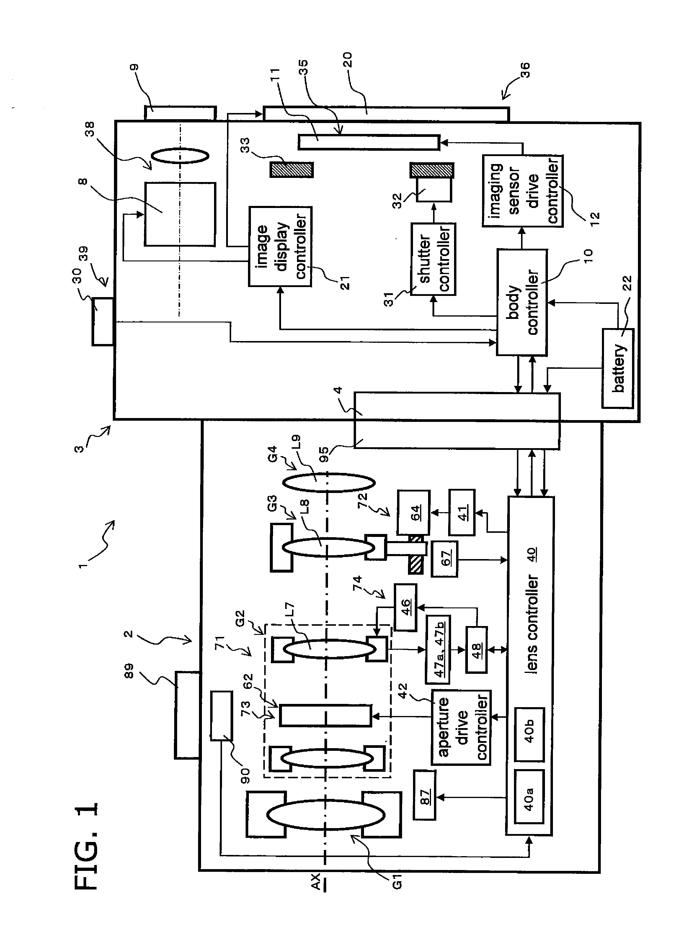
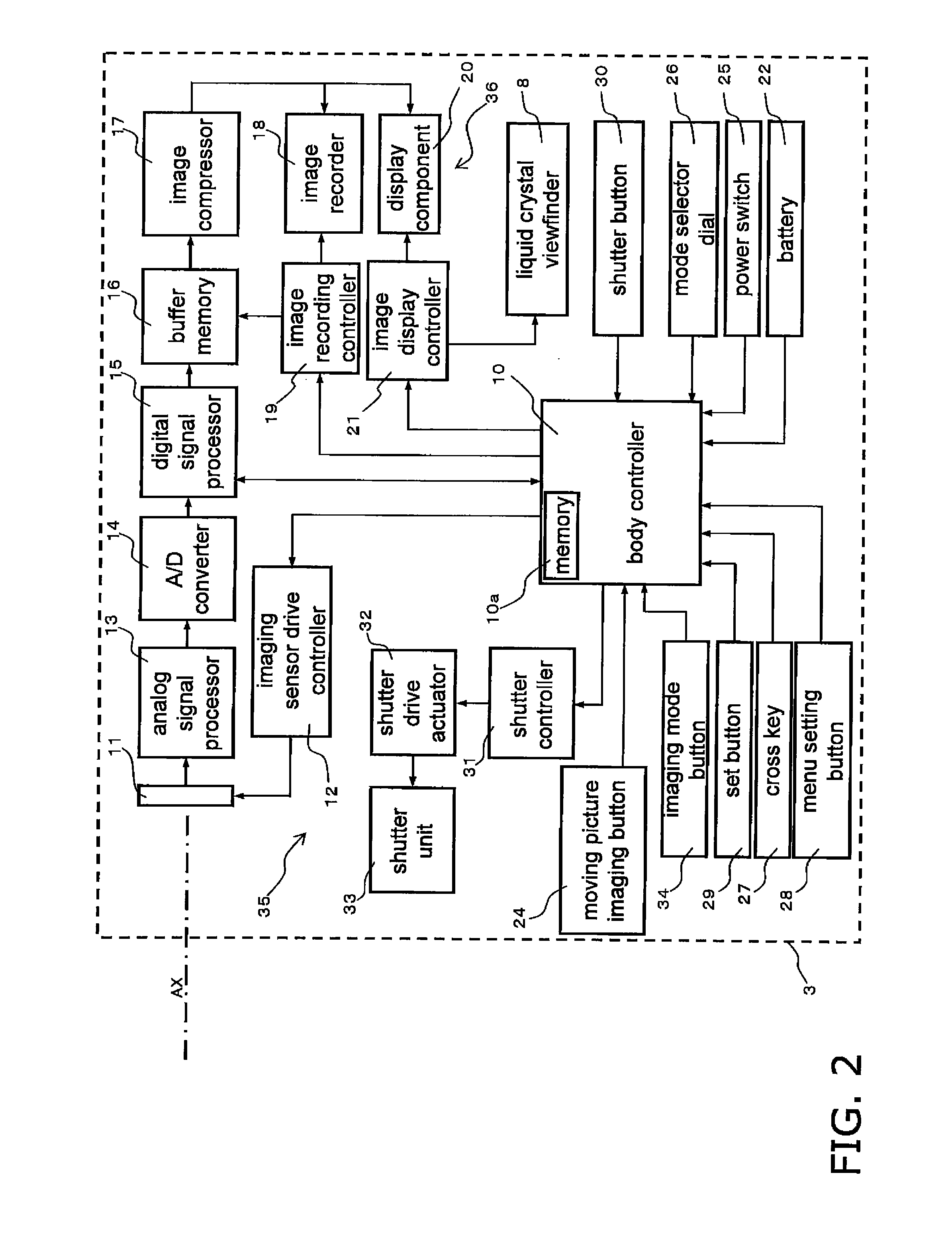
[0043]A digital camera 1 will be described through reference to FIGS. 1 to 3B. As shown in FIG. 1, the digital camera 1 (one example of an imaging device) is an interchangeable lens type of digital camera, and mainly comprises a camera body 3 (one example of a camera body) and an interchangeable lens unit 2 (one example of a lens barrel) that is removably mounted to the camera body 3. The interchangeable lens unit 2 is removably mounted to a body mount 4 provided to the front face of the camera body 3, via a lens mount 95.

[0044]This digital camera 1 is what is known as a mirror-less single-lens camera, in which no quick-return mirror is installed between the body mount 4 and an imaging sensor 11.

[0045]Simplified Configuration of Interchangeable Lens Unit

[0046]The simplified configuration of the interchangeable lens unit 2 will be described through reference to FIG. 1 and FIGS. 4 to 7. As shown in FIG. 1, the interchangeable lens unit 2 has an optical ...

second embodiment

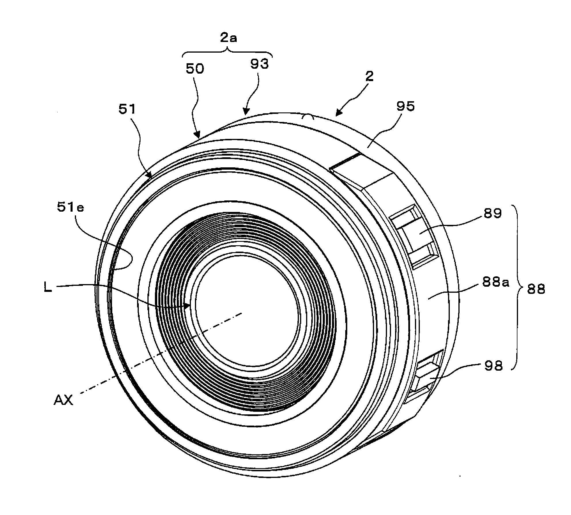
[0253]In the first embodiment given above, the zoom lever 89 and the focus lever 98 are used to change the focal distance and adjust the focus. However, changing the focal distance may be accomplished using a zoom ring, and focusing may be accomplished using a focus ring. An interchangeable lens unit 302 pertaining to a second embodiment will now be described, using a zoom ring as an example.

[0254]Those components that have substantially the same function as those in the first embodiment above will be numbered the same and will not be described in detail again.

[0255]The interchangeable lens unit 302 shown in FIG. 21 is equipped with a zoom ring unit 388. The zoom ring unit 388 has a stop ring 388a (one example of a restricting member) and a zoom ring 389 (one example of an interface member). The stop ring 388a is an annular member, and is mounted to the end on the subject side of a fixed frame 350. The stop ring 388a can also be said to be disposed on the opposite side of the fixed ...


PUM


Abstract

An interchangeable lens unit is provided that includes a lens housing, a cam frame, a zoom motor mounted to the lens housing, and a transmission mechanism. The zoom motor has a zoom driveshaft that outputs a driving force. The transmission mechanism is configured to transmit the driving force from the zoom driveshaft to the cam frame. The lengthwise direction of the zoom motor is oriented differently than the direction of the optical axis. When viewed along the direction of the optical axis, the zoom motor is disposed on the inner peripheral side of the cam frame.

Description

CROSS-REFERENCE TO RELATED APPLICATIONS[0001]This application is a continuation of PCT Patent Application No. PCT / JP2011 / 003039, which claimed priority to Japanese Patent Application No. 2011-026549, filed on Feb. 9, 2011. The entire disclosure of PCT Patent Application No. PCT / JP2011 / 003039 and Japanese Patent Application No. 2011-026549 are hereby incorporated herein by reference.BACKGROUND[0002]1. Technical Field[0003]The technology disclosed herein relates to a lens barrel used in an imaging device.[0004]2. Description of the Related Art[0005]Imaging devices that produce image data about a subject have rapidly been gaining popularity in recent years. A lens barrel for adjusting the focal distance is installed in an imaging device. Known imaging devices include, for example, integrated types of cameras and those with an interchangeable lens. Integrated cameras have the lens barrel built in. An interchangeable lens camera has a camera body and an interchangeable lens unit that can...

Claims


Application Information

Patent Timeline
Patent Type & Authority Applications(United States)
IPC IPC(8): H04N5/225G02B7/04
CPCG02B7/08G03B2205/0092G03B2205/0046G03B3/10G03B2205/00
Inventor ITO, DAISUKE
Owner PANASONIC CORP
Why Eureka
Try Eureka