
Vehicle headlamp

a headlamp and vehicle technology, applied in the field of vehicle headlamps, can solve the problems of reducing the amount of forward light irradiated, deteriorating sealing properties of the lamp outer casing, and forming gaps between the lamp housing and the heat sink, so as to reduce the manufacturing cost and the size of the vehicle headlamp

Inactive Publication Date: 2012-08-09
KOITO MFG CO LTD
View PDF3 Cites 24 Cited by
  • Summary
  • Abstract
  • Description
  • Claims
  • Application Information

AI Technical Summary

Benefits of technology

[0013]One of illustrative aspects of the present invention is to secure a sealing property in a lamp outer casing, and to improve a heat-radiation property.
[0015]Accordingly, the heat sink is not moved together with the lens unit during aiming adjustment, and it is possible to secure a sealing property in the lamp outer casing and to improve a heat-radiation property.
[0017]Accordingly, it is possible to reliably perform aiming adjustment by a simple structure.
[0019]Accordingly, since the second aiming operation shaft used to perform aiming adjustment is also used as the drive shaft used to perform leveling adjustment, it is possible to reduce the size of the vehicle headlamp through the reduction of the number of components.
[0021]Since one light source unit includes the driving circuit and the light source driven by the driving circuit, it is possible to reduce the manufacturing costs and the size of the vehicle headlamp.

Problems solved by technology

For this reason, there is a concern that a gap is formed between the lamp housing and the heat sink.
If a gap is formed between the lamp housing and the heat sinks, a sealing property in the lamp outer casing deteriorates.
For this reason, there is a possibility that the amount of light irradiated forward is reduced or the smooth operation of each part is hindered by the penetration of dust or moisture into the lamp outer casing.

Method used


Image

  • Vehicle headlamp
  • Vehicle headlamp
  • Vehicle headlamp

Examples


Embodiment Construction

[0029]A vehicle headlamp according to exemplary embodiments of the invention will be described below with reference to the accompanying drawings.

[0030]Vehicle headlamps 1 are mounted on both left and right end portions of a front end portion of a vehicle body.

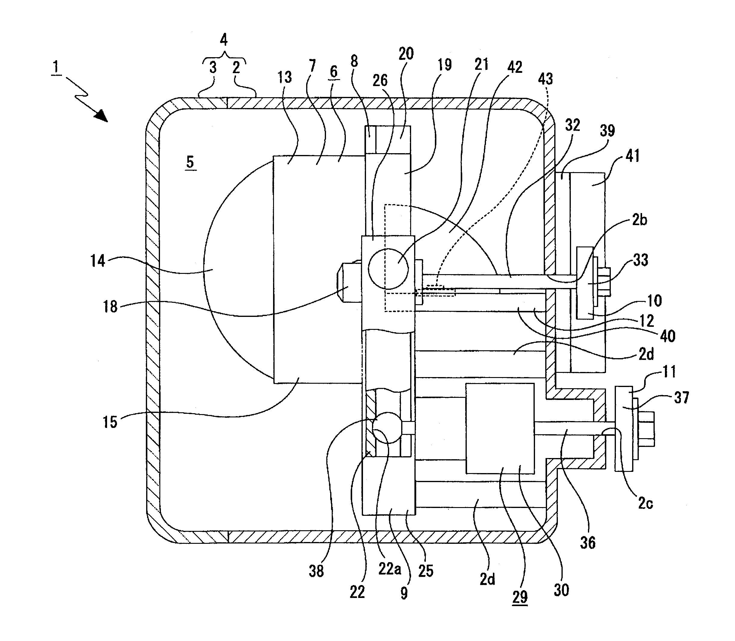
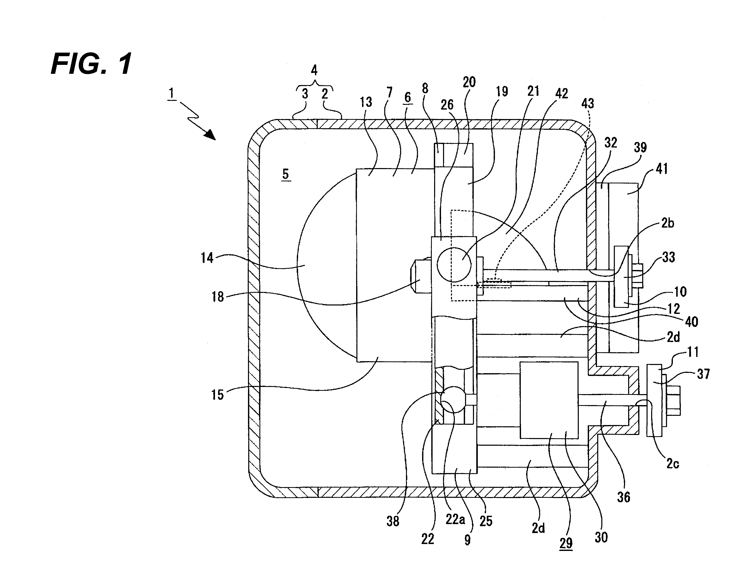
[0031]As shown in FIG. 1, the vehicle headlamp 1 includes a lamp housing 2 and a cover 3. The lamp housing 2 includes a recess that is opened to the front side, and the cover 3 closes an opening of the lamp housing 2. The lamp housing 2 and the cover 3 form a lamp outer casing 4. An inner space of the lamp outer casing 4 is formed as a lamp chamber 5.

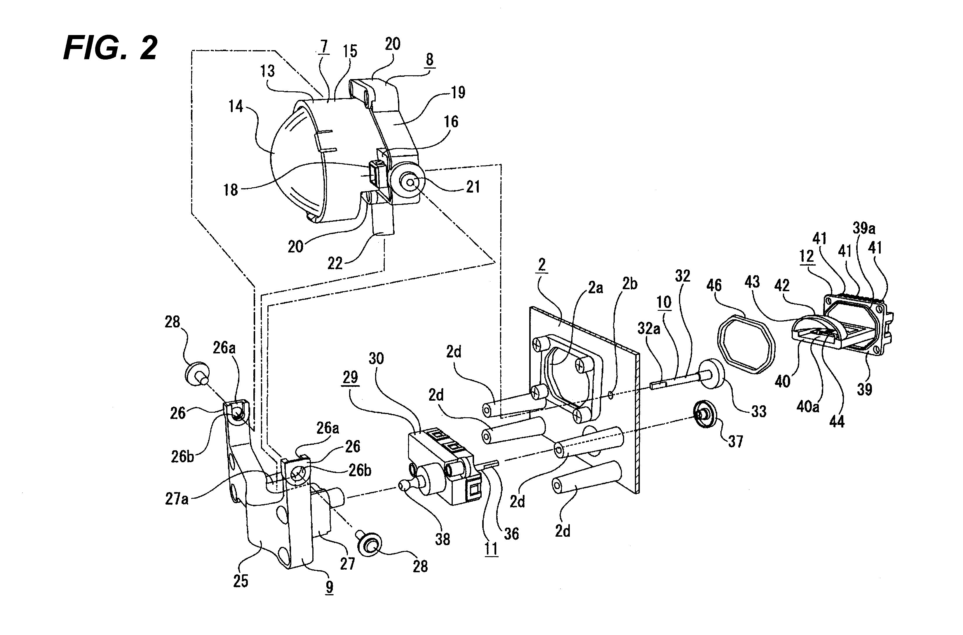
[0032]A mounting hole 2a, which passes through the lamp housing in a longitudinal direction of a vehicle, is formed at the rear end portion of the lamp housing 2 (see FIG. 2). Shaft insertion holes 2b and 2c, which pass through the lamp housing in the longitudinal direction, are formed at the rear end portion of the lamp housing 2. The shaft insertion holes 2b and 2c are positioned...


PUM


Abstract

A vehicle headlamp includes: a lamp outer casing; a lamp unit including: a light source unit having a light source that emits light, a reflector and a heat sink; a stationary frame; a movable frame that is supported by the stationary frame to be rotatable about a rotating shaft; a lens unit supported by the movable frame and having a projection lens; a first aiming operation shaft that adjusts an optical axis in the lateral direction; and a second aiming operation shaft that adjusts the optical axis in the vertical direction. A focal point of the light reflected by the reflector is coincident with a center of the rotating shaft. The lens unit is moved relative to the stationary frame such that a distance between the focal point and the projection lens is constant. The heat sink is positioned on the outside of the lamp outer casing.

Description

CROSS-REFERENCE TO RELATED APPLICATION[0001]This application claims priority from Japanese Patent Application No. 2011-021629, filed on Feb. 3, 2010, the entire contents of which are hereby incorporated by reference.BACKGROUND[0002]1. Technical Field[0003]The present disclosure relates to a vehicle headlamp. More particularly, the present disclosure relates to a technical field that secures a sealing property in a lamp outer casing and improves a heat-radiation property by fixing a light source unit to a lamp housing while heat sinks are positioned on the outside of a lamp outer casing.[0004]2. Related Art[0005]As a vehicle headlamp, there is, for example, a vehicle headlamp where a lamp unit is disposed in a lamp outer casing including a lamp housing and a cover. The lamp unit includes a lens unit that includes a projection lens projecting light emitted from a light source to the front side and a lens holder holding the projection lens.[0006]As this vehicle headlamp, there is a veh...

Claims


Application Information

Patent Timeline
Patent Type & Authority Applications(United States)
IPC IPC(8): B60Q1/04
CPCB60Q1/0683F21S48/1721F21S41/19F21S41/295F21S41/635
Inventor SHIBATA, HIROKITATSUKAWA, MASASHITAKEDA, HITOSHIOISHI, KAZUTAMI
Owner KOITO MFG CO LTD
Learn More