Decrypting apparatus, encrypting apparatus, decrypting method, encrypting method, and communication system

a technology of encrypting apparatus and communication system, which is applied in the direction of synchronising transmission/receiving encryption devices, secret communication, digital transmission, etc., and can solve problems such as packet loss and reverse arrival order, and the inability of the internet to meet real-time communication, and the increase of the communication speed of the internet does not necessarily improve the real-time characteristi

Active Publication Date: 2012-08-09
PANASONIC CORP
View PDF4 Cites 15 Cited by
  • Summary
  • Abstract
  • Description
  • Claims
  • Application Information

AI Technical Summary

Benefits of technology

[0010]The decrypting apparatus receives the packet information used for generating the key and the plaintext data encrypted by using the key both in a single packet, hence utilizing information which is necessary for generating the key also for decryption of the cryptography data. As a result, even when packet loss and a change in an order of the packets occur during the transmission of the packets, the apparatuses prevent a synchronization gap between the encrypting apparatus and the decrypting apparatus.

Problems solved by technology

Since Quality of Service (QoS) is not taken into consideration in the Internet, the Internet is not suitable for the real-time communication.
The number of users and a transmission data capacity abruptly increase (for example, high definition in image communication), and thus, the increasing of the communication speed of the Internet does not necessarily improve the real-time characteristic.
However, the UDP communication may cause a packet loss and a reverse arrival order of packets, hence requiring a particular technique for a common key cryptosystem.
For example, in an AES CBC mode of Arcfour encryption and block encryption of streaming encryption which are often utilized in the common key cryptosystem of the SSL cryptographic communication (TCP communication), the packet loss and the reversed arrival order of packets may cause a synchronization gap, and may prevent the receiving side from performing proper decryption from the time the packet loss and the reversed arrival order of packets occur.

Method used


Image

  • Decrypting apparatus, encrypting apparatus, decrypting method, encrypting method, and communication system
  • Decrypting apparatus, encrypting apparatus, decrypting method, encrypting method, and communication system
  • Decrypting apparatus, encrypting apparatus, decrypting method, encrypting method, and communication system

Examples


embodiment 1

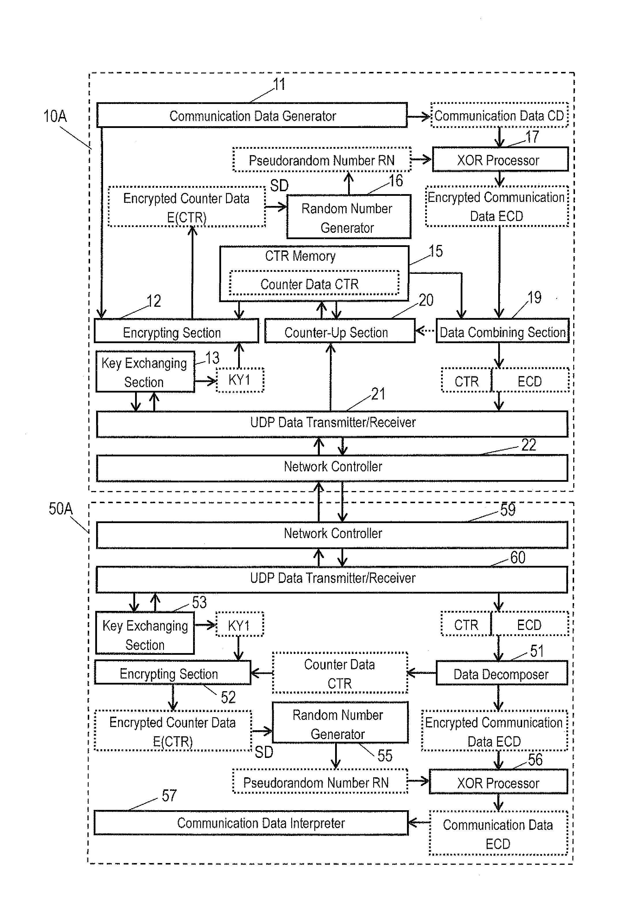
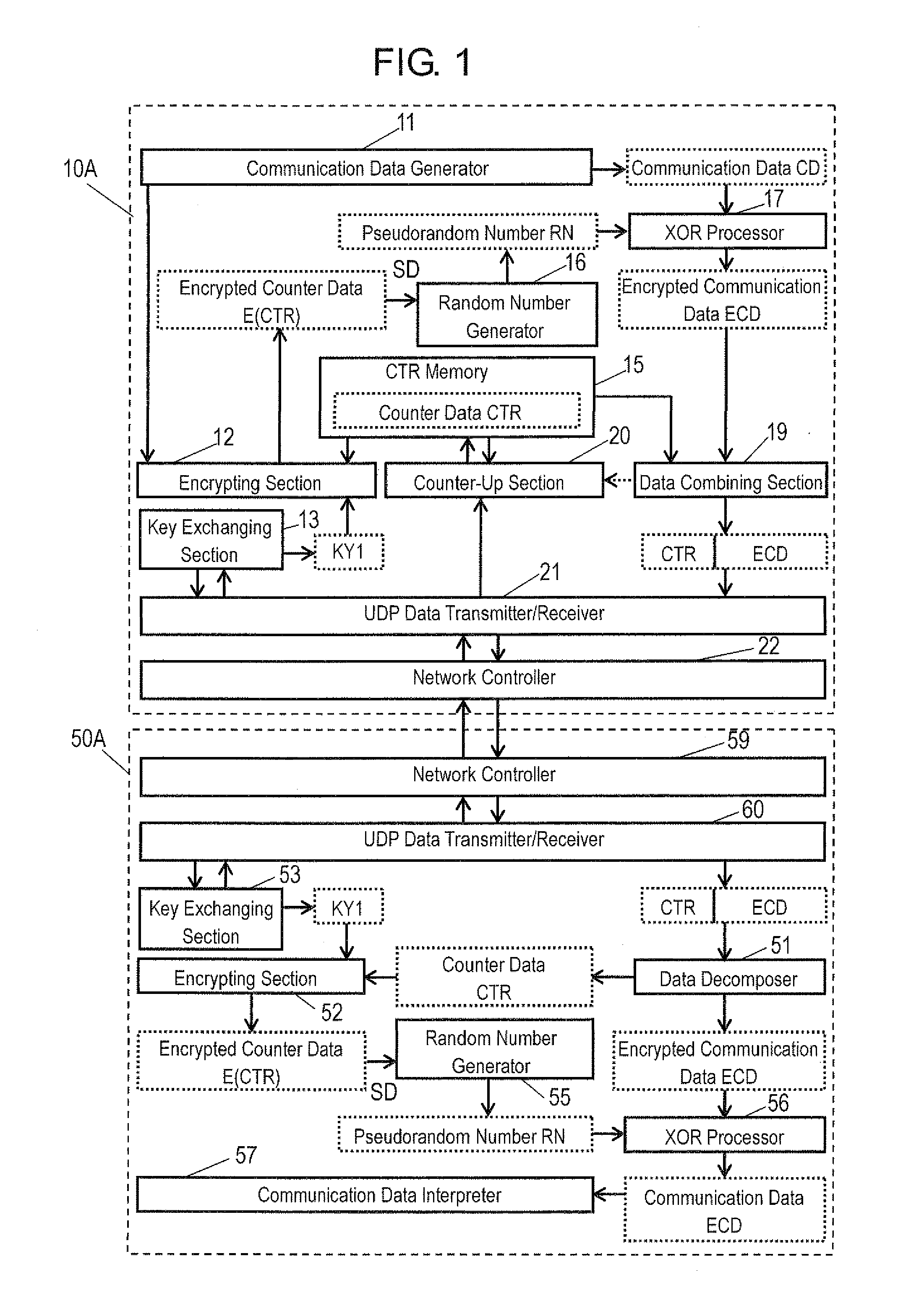
[0034]A communication system shown in FIG. 1 includes transmitter 10A and receiver 50A. Transmitter 10A and receiver 50A are examples of the encrypting apparatus and the decrypting apparatus, respectively. Transmitter 10A and receiver 50A can be connected via a communication path, such as the Internet. The communication path may be any of wired and wireless paths. According to this embodiment, a connectionless type protocol, such as the User Datagram Protocol (UDP) is used as a communication protocol. A connection type protocol, such as the Transmission Control Protocol (TCP) can be used as the communication protocol.

[0035]Transmitter 10A includes communication data generator 11, encrypting section 12, key exchanging section 13, CTR memory 15, random number generator 16, XOR processor 17, data combining section 19, counter-up section 20, UDP data transmitter / receiver 21, and network controller 22. Transmitter 10A includes an integrated circuit, such as a CPU or an ASIC. Functional b...

embodiment 2

[0102]An operation of a communication system according to Exemplary Embodiment 2 will be described with reference to FIG. 11. The communication system according to Embodiment 2 is the same as the communication system according to Embodiment 1 shown in FIG. 1, but is different from Embodiment 1 in its operating method as described below.

[0103]The operating method shown in FIG. 11 has two different points than the operation method shown in FIG. 2. The first different point is that the random number generator changes a seed for a predetermined packet. For example, when the counter data exceeds a predetermined value or when a number of all communication data in the packet transmitted to the receiving side exceeds a predetermined value, the seed is changed.

[0104]The second different point is that the receiver can obtain the number of all communication data from a predetermined packet to a certain packet transmitted. For example, the transmitter describes, in the UDP data area of each of ...

embodiment 3

[0134]FIG. 14 is a schematic view of a monitoring system according to Exemplary Embodiment 3. FIG. 14 illustrates monitoring system 1 that is a communication system. Monitoring system 1 includes personal computer (PC) 50C and network camera 10C. PC 50C and network camera 10C are connected via network cable 205. PC 50C is a receiver receiving images. Monitor 203 displays the received images. Network controller 59 and key setting section 53 are adapted to be connected externally to PC 50C. Network controller 59 is connectable to a network cable, and controls network communication. Key setting section 53 exchanges key data with an external memory, such as a universal serial bus (USB) interface, and sets a key.

[0135]Network camera 10C is a transmitter performing monitoring. Network camera 10C includes camera section 101 and network controller 22. Key setting section 13 are adapted to be connected externally to network camera 10C. Camera section 101 captures an image, and generates image...


PUM


Abstract

A decrypting apparatus for decrypting cryptography data included in a packet includes a receiver, a key generator, and a decrypting section. The receiver receives a packet transmitted from an encrypting apparatus that executes an encrypting process. The key generator generates a key used for the encrypting process. The decrypting section decrypts cryptography data included in the packet received by the receiver with using the key generated by the key generator. In the decrypting apparatus, the packet received by the receiver includes packet information used for generating the key. The key generator generates the key with using the packet information.

Description

TECHNICAL FIELD [0001]The present invention relates to a decrypting apparatus, an encrypting apparatus, a decrypting method, an encrypting method, and a communication system that can repress a synchronization gap between a transmitting side and a receiving side even in a communication system where a packet loss and a reverse arrival order of packets may occur.BACKGROUND ART [0002]The Internet has recently been utilized for various communications. E-mail and Web as non-real-time communication were mainly used when the Internet started spreading. According to advances in Internet technology, however, real-time communication in sound and image systems, such as a television, a telephone, and a monitoring camera, is recently used a lot in the Internet.[0003]Since Quality of Service (QoS) is not taken into consideration in the Internet, the Internet is not suitable for the real-time communication. Therefore, the Internet is demanded to have a high communication speed in order to improve a...

Claims


Application Information

Patent Timeline
Patent Type & Authority Applications(United States)
IPC IPC(8): H04L9/00
CPCH04L9/0662H04L9/12H04L63/0428H04L63/06
Inventor MATSUO, MASAKATSU
Owner PANASONIC CORP
Why Eureka
Try Eureka