

Thrust generating apparatus
a technology of thrust generating apparatus and thrust cylinder, which is applied in the direction of piston pump, marine propulsion, vessel construction, etc., can solve the problems of diesel engine air pollution in terms of environmental performance, and achieve the effects of improving the strength of the propeller blade, improving maintenance efficiency, and easy replacemen
- Summary
- Abstract
- Description
- Claims
- Application Information
AI Technical Summary
Benefits of technology
Problems solved by technology
Method used
Image

Examples
embodiment 1
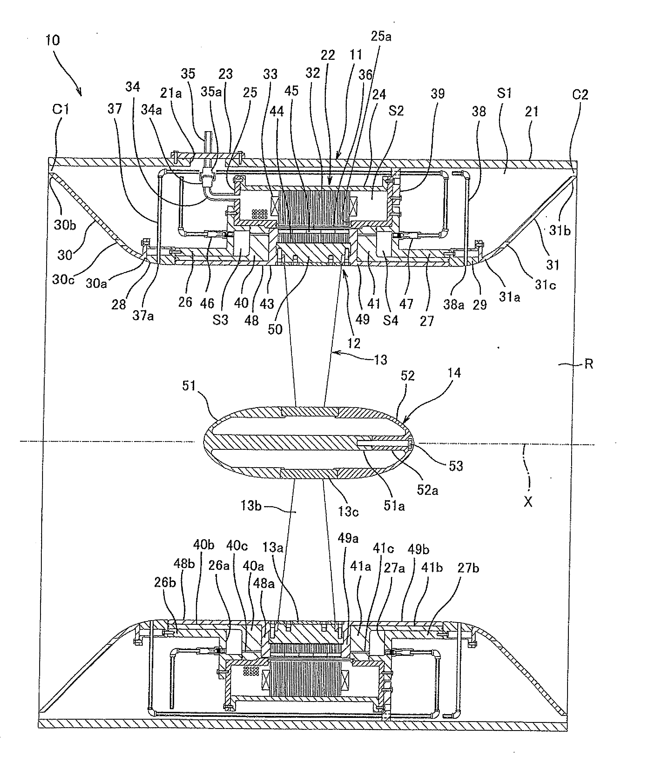
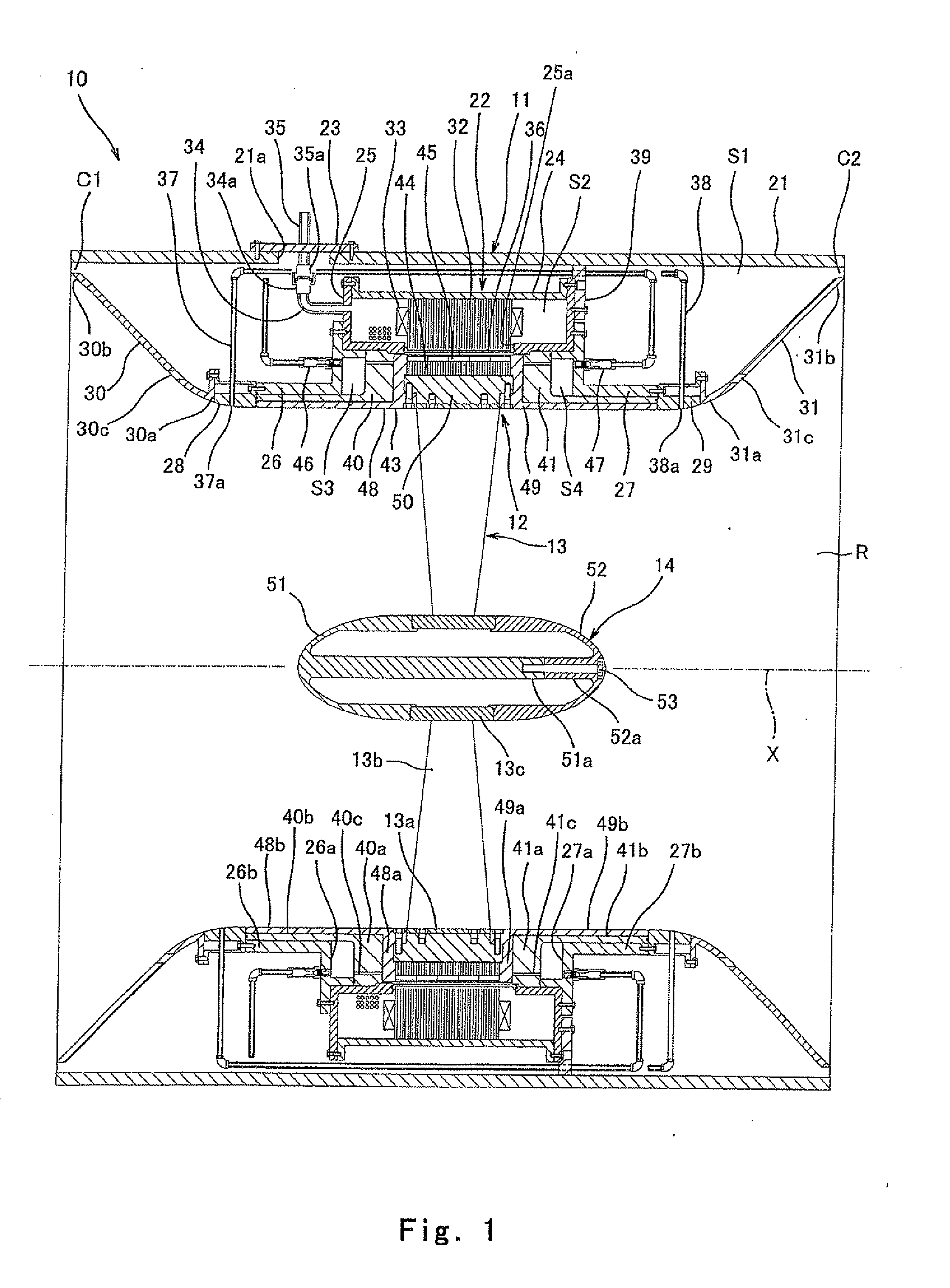
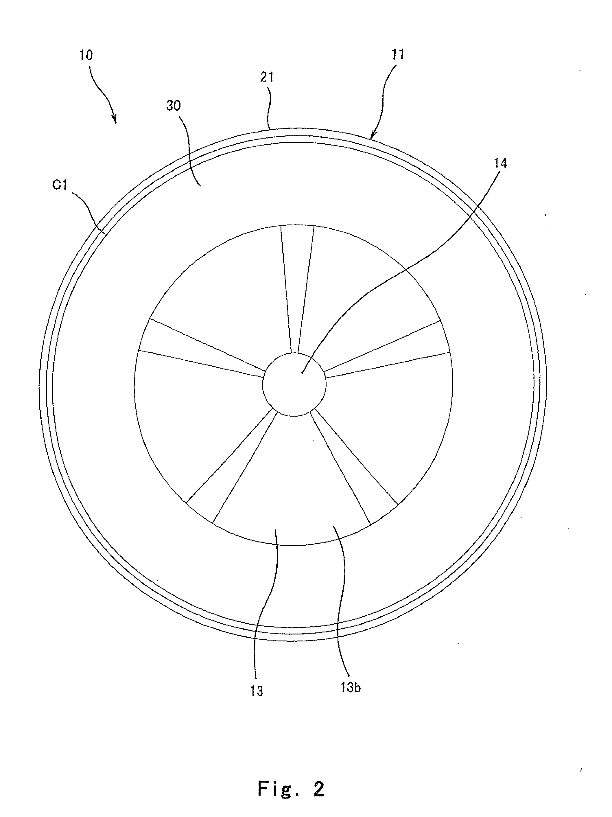
[0020]As shown in FIGS. 1 and 2, a thrust generating apparatus 10 of Embodiment 1 includes: an annular stator 11 fixed to a hull; an annular rotor 12 capable of rotating positively and negatively relative to the stator 11; a propeller member 13 formed integrally with the rotor 12 on a radially inner side of the rotor 12; and a boss 14 formed integrally with a radially inner tip end of the propeller member 13 and provided on a rotation axis line X of the rotor 12.
[0021]The stator 11 includes an annular outer casing 21 and an annular inner casing 22 provided on an inner periphery side of the outer casing 21. A substantially cylindrical space formed between the outer casing 21 and the inner casing 22 is a cooling space S1. The outer casing 21 is a cylindrical duct on which a cable through hole 21a is partially formed. The cable through hole 21a is closed by a lid 23. The inner casing 22 is formed by coupling first to fourth casings 24 to 27, support rings 28 and 29, and fairings 30 and...
embodiment 2
[0039]As shown in FIGS. 4 and 5, a stator 111 of a thrust generating apparatus 110 of Embodiment 2 includes an annular outer casing 121 and an annular inner casing 22 provided on an inner periphery side of the outer casing 121. A cylindrical space formed between the outer casing 121 and the inner casing 22 is the cooling space S 1. The outer casing 121 includes: a casing main body 130 including an upper surface opening 130i; and a cover 131 configured to close the upper surface opening 130i of the casing main body 130. Since components of the thrust generating apparatus 110 are the same as those of Embodiment 1 except for the outer casing 121, the same reference signs are used for the same components, and detailed explanations thereof are omitted.
[0040]The casing main body 130 includes: vertical wall portions 130a and 130b opposed to each other in the left-right direction; inner cylindrical portions 130d and 130e, each of which projects in the outward direction along the rotation ax...
embodiment 3
[0042]As shown in FIGS. 6 and 7, according to the thrust generating apparatus of Embodiment 3, the propeller blades of a propeller member 113 can be disassembled individually. Since the components except for the propeller member 113 and a boss 114 are the same as those of Embodiment 1 or 2, explanations thereof are omitted.
[0043]The propeller member 113 is constituted by assembling a plurality of (for example, six) separable propeller members 170. Each of the separable propeller members 170 includes: a circular-arc plate portion 170a on which bolt holes 170d are formed; a propeller blade 170b projecting in the radially inward direction from the circular-arc plate portion 170a ; and a stopper protrusion portion 113c projecting in the radially inward direction from a radially inward tip end of the propeller blade 170b.
[0044]The boss 114 includes a pair of separable bosses 151 and 152 configured to be separable in both directions along the rotation axis line X. Each of the separable b...
PUM
 Abstract
Description
Claims
Application Information