Method for producing a fuel injection valve, and fuel injection valve
- Summary
- Abstract
- Description
- Claims
- Application Information
AI Technical Summary
Benefits of technology
Problems solved by technology
Method used
Image
Examples
Embodiment Construction
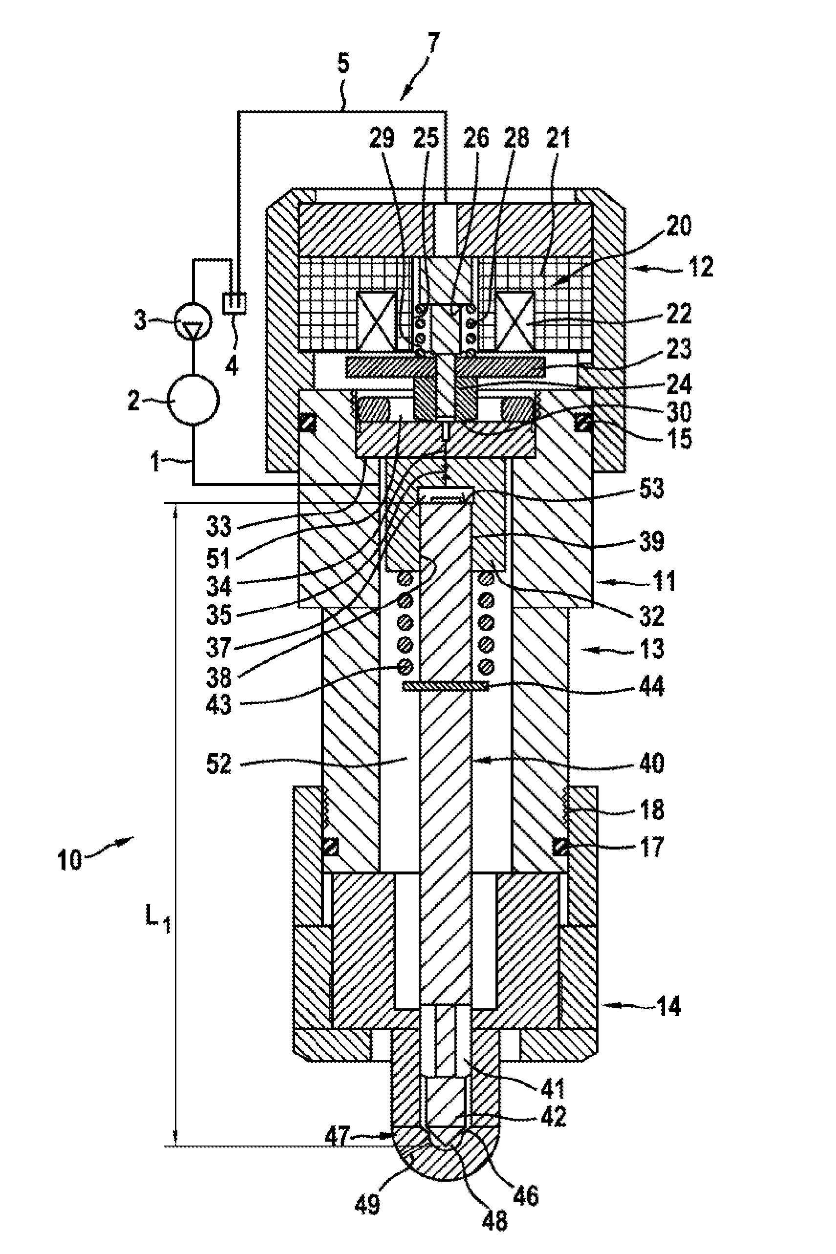
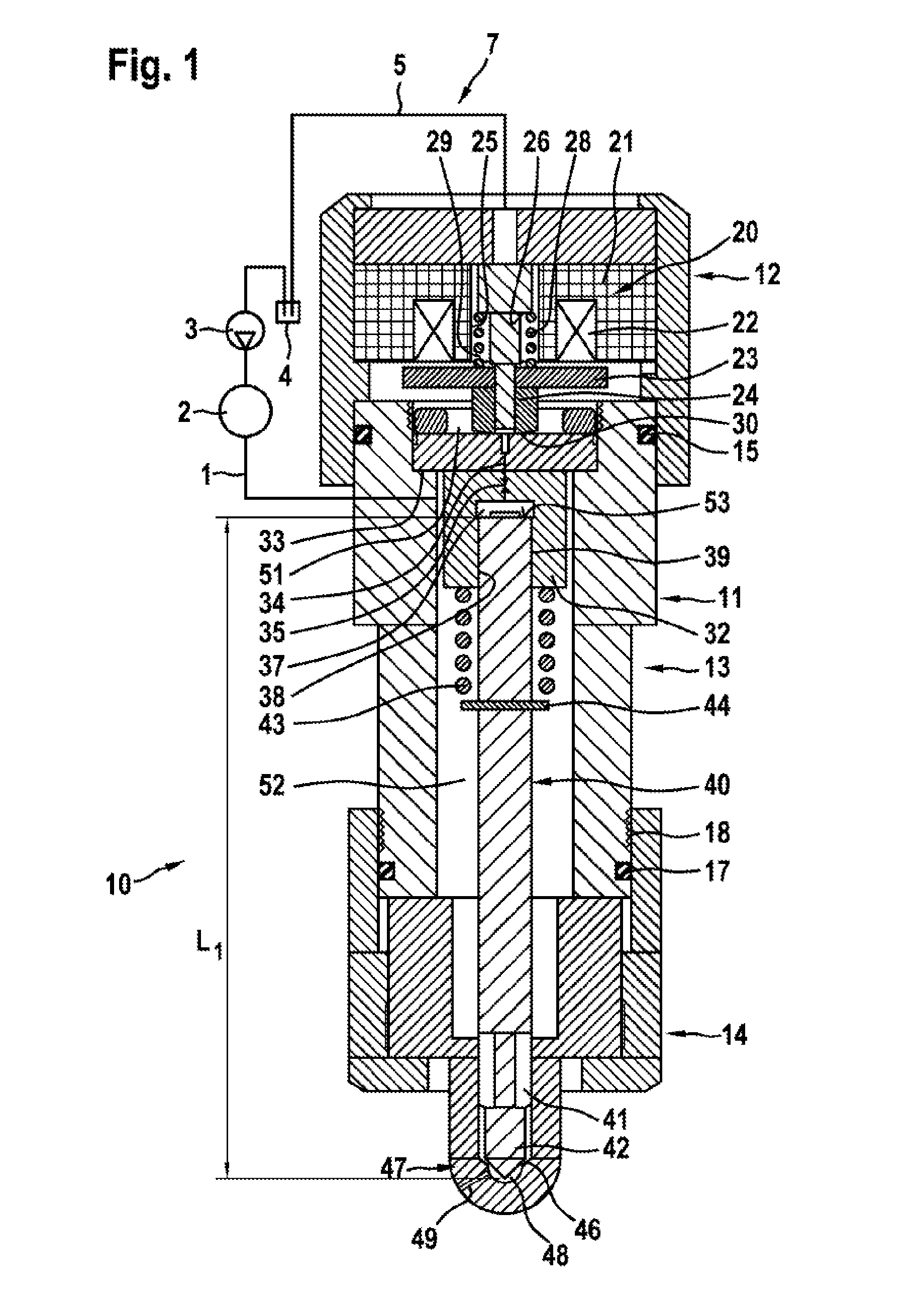
[0016]FIG. 1 illustrates a first fuel injection valve 10, such as is used in particular in so-called common rail injection systems. Here, the fuel injection valve 10 is connected via a supply line 1 to a fuel accumulator, a so-called rail 2. Fuel at high pressure, for example a pressure of approximately 2000 bar, is stored in the rail 2. Here, the rail 2 is connected to a high-pressure fuel pump 3 which sucks fuel out of a fuel store, in particular a fuel tank 4, and compresses said fuel. Fuel not required by the fuel injection valve 10 is returned to the fuel tank 4 again via a return line 5 which is at low pressure.
[0017]A fuel injection system 7 as described has a separate fuel injection valve 10 for each cylinder of an internal combustion engine, which fuel injection valves are all connected to the rail 2.
[0018]The fuel injection valve 10 has an injector housing denoted as a whole by 11. Here, the elongate injector housing 11 is composed of three assemblies: a standardized upper...
PUM
| Property | Measurement | Unit |
|---|---|---|
| Diameter | aaaaa | aaaaa |
| Length | aaaaa | aaaaa |
| Volume | aaaaa | aaaaa |
Abstract
Description
Claims
Application Information
 - R&D
- Intellectual Property
- Life Sciences
- Materials
- Tech Scout
- Unparalleled Data Quality
- Higher Quality Content
- 60% Fewer Hallucinations
Browse by: Latest US Patents, China's latest patents, Technical Efficacy Thesaurus, Application Domain, Technology Topic, Popular Technical Reports.
© 2025 PatSnap. All rights reserved.Legal|Privacy policy|Modern Slavery Act Transparency Statement|Sitemap|About US| Contact US: help@patsnap.com


