

Aircraft horizontal stabiliser fitted with leading-edge strake
- Summary
- Abstract
- Description
- Claims
- Application Information
AI Technical Summary
Benefits of technology
Problems solved by technology
Method used
Image

Examples
first embodiment
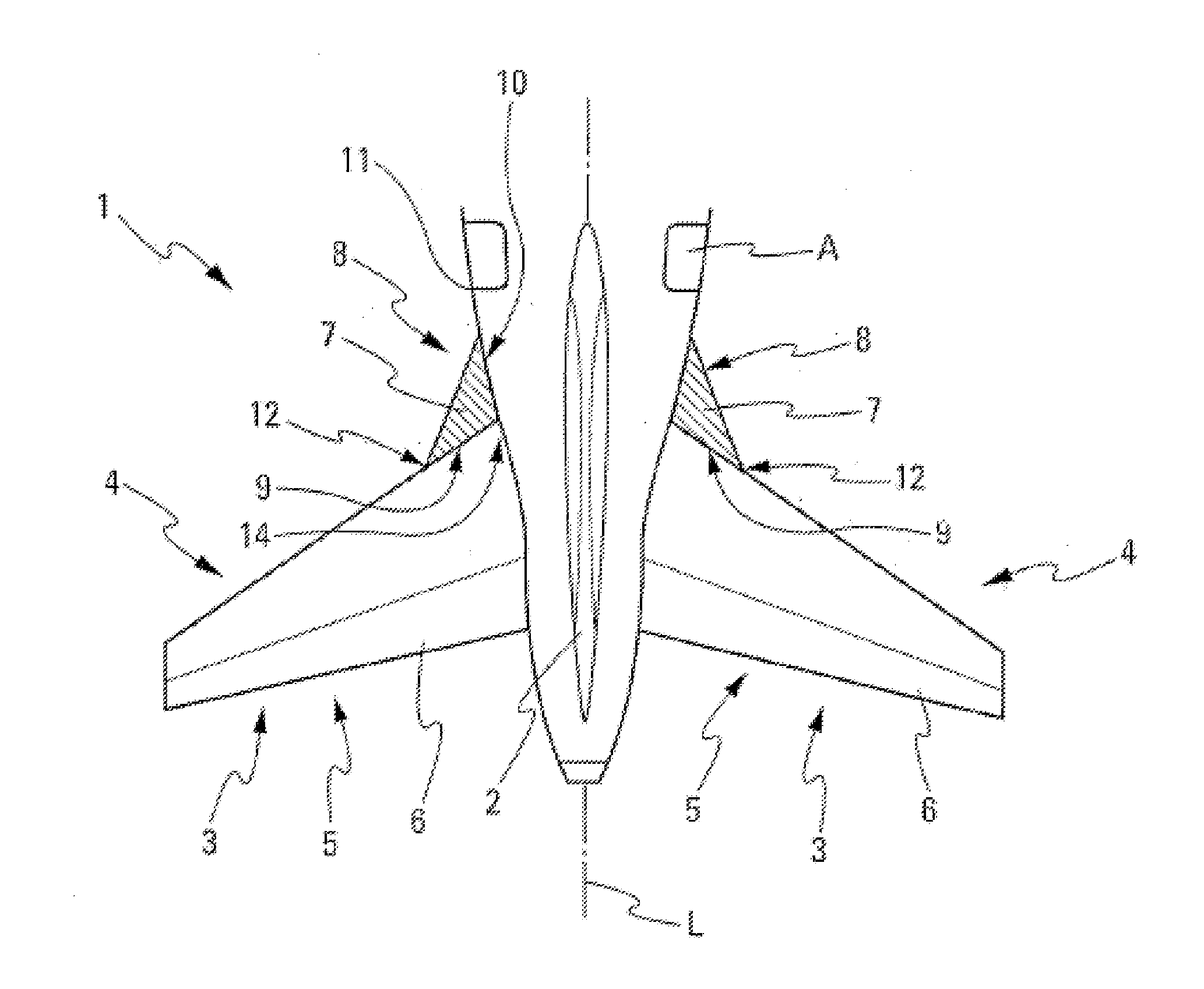
[0056]With a particular view to reducing the drag on aircraft A, each horizontal stabiliser 3 has, according to the invention, a strake 7 which represents a generally flat aerodynamic surface comprising three points which define a leading edge 8, a trailing edge 9 and an edge 10 intended for the root. The trailing edge 9 of each strake 7 is integral with the leading edge 4 of the horizontal stabiliser 3 at the latter's root 14; in other words, inboard at the fuselage 11 of aircraft A. Furthermore, according to the invention, the strake 7 has, at the root 14, a sweep angle that is significantly greater than that of the horizontal stabiliser 3. The leading edge 8 of the strake 7 has, at the junction 12 of the said leading edge 8 with the leading edge 4 of the horizontal stabiliser, a sweep angle greater than 45°.
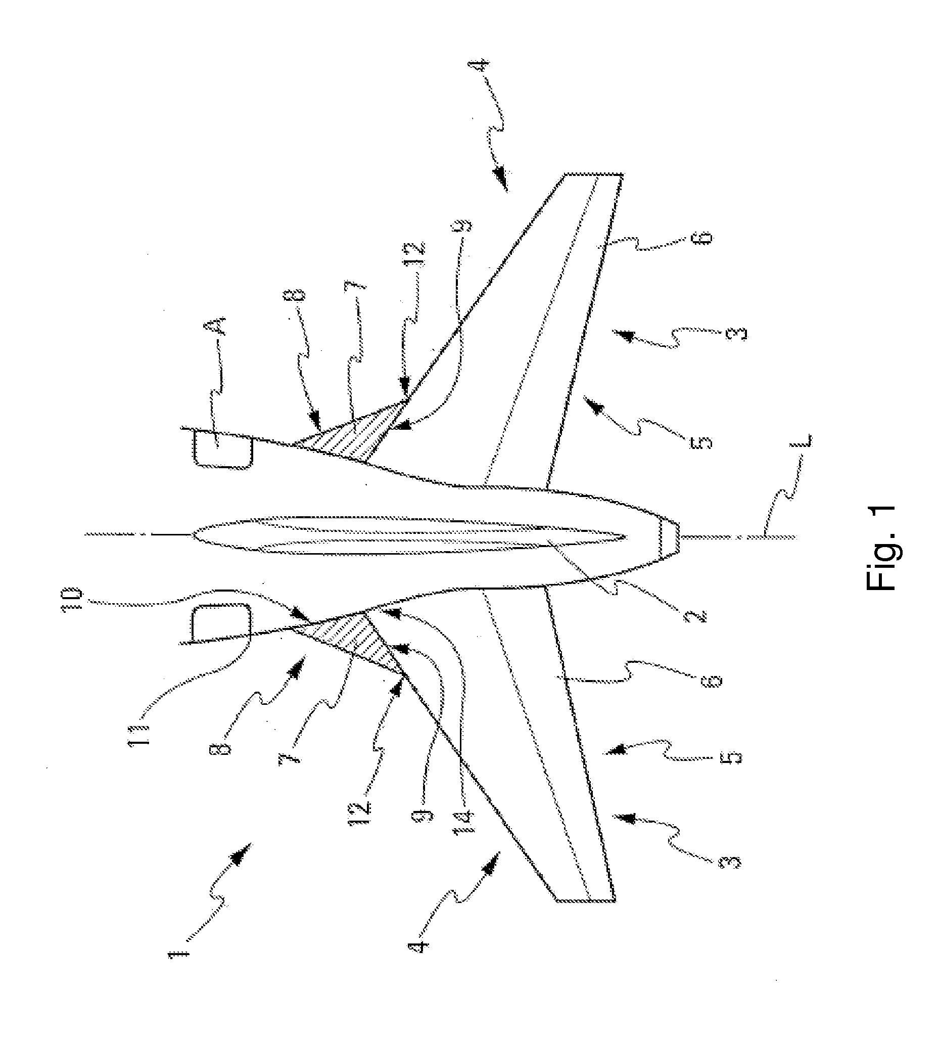
[0057]This type of strake 7 allows the creation of vortices 13 at a high angle of attack as shown in FIG. 2. Flow separations generally appear on the outer part of the horizon...
second embodiment
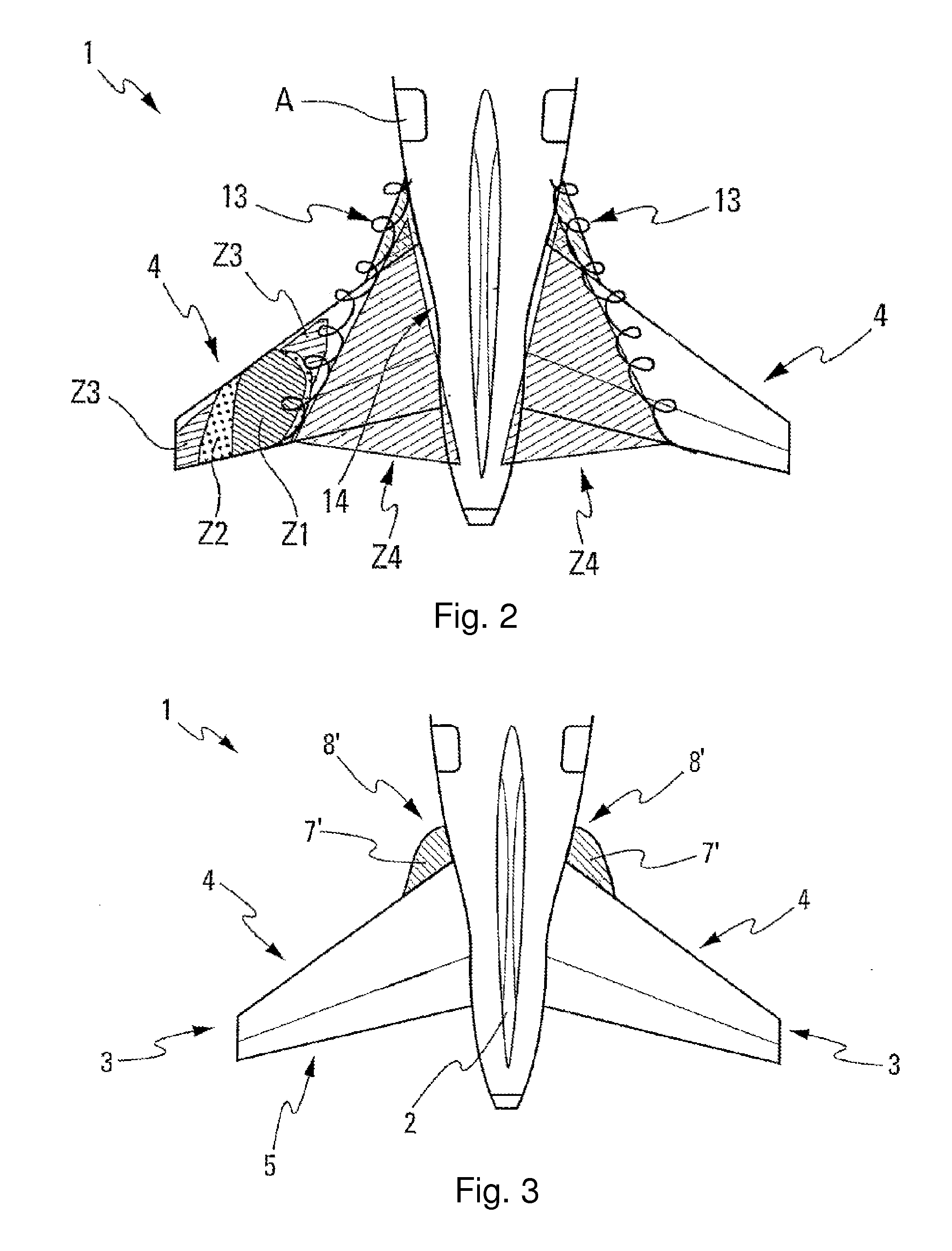
[0058]In the context of the present invention, the strake 7 can be produced in a number of sizes and shapes. In particular, the leading edge 8 of the strake 7 can be:[0059]straight as shown in FIG. 1; or[0060]curved (the strake 7′ of the second embodiment has a curved leading edge 8′, while retaining a sweep angle that has the above-mentioned characteristics of the junction 12), as shown in FIG. 3.
[0061]Furthermore, the present invention can be applied to any type of horizontal stabiliser 3, in particular:[0062]a fixed horizontal stabiliser that is fitted to the fuselage of the aircraft;[0063]a horizontal stabiliser with a moving part (control surface 6), which is also fitted to the fuselage of the aircraft A, as shown in FIGS. 1 to 3;[0064]a fixed or movable horizontal stabiliser fitted on the top of the aircraft's tail fin;[0065]a fixed or movable horizontal stabiliser fitted in an intermediate position on the fin.
[0066]A practical problem for a movable horizontal stabiliser, e.g....
third embodiment
[0068]FIG. 4 illustrates schematically the invention and shows the horizontal stabiliser 3 with a ‘gothic’ shaped strake 7″. The horizontal stabiliser 3 is movable and may be either an adjustable horizontal stabiliser with an elevator (not shown) identical or similar to that shown in FIG. 1, or alternatively may be an all-moving horizontal stabiliser (or stabilator). The horizontal stabiliser 3 is hinged for movement with respect to the aircraft A so as to vary the angle of incidence of the stabiliser 3 with respect to the aircraft fuselage 11 (not shown in FIG. 4).
[0069]The movable horizontal stabiliser 3 may be mounted on the aircraft fuselage 11 (empennage) as shown in FIG. 1, or alternatively may be mounted on the fin 2 (not shown in FIG. 4) either adjacent the tip to provide a “T-tail” configuration, or intermediate the tip and root of the fin to provide a “cruciform tail” configuration.
[0070]The ‘gothic’ shaped strake 7″ has a leading edge 8″, which creates a streamwise vortex...
PUM
 Abstract
Description
Claims
Application Information