Detector Controlled Illuminating System

Active Publication Date: 2012-08-16
YECHEZKAL EVAN SPERO
View PDF24 Cites 754 Cited by
  • Summary
  • Abstract
  • Description
  • Claims
  • Application Information

AI Technical Summary

Benefits of technology

[0056]The present invention also relates to lighting fixtures comprised of many directional light sources that are mounted with different aimings so as to correctly illuminate an area. The LED light sources are moveable so that they can be adjusted to best illuminate the area where the luminaire has actually been installed. In addition they may be controllable by a microprocessor as to the light intensity and color so as to best assist people to see what they are doing at that moment, be it reading a book, watching TV or assembling an automobile. The lighting fixture is equipped with a “smart” camera (similar to a cell phone's processor controlled digital camera) which inputs data on the lighting, occupants and current conditions within the room. The result of this added sophistication is that electricity is spent on generating only useful light. The energy savings greatly reduces electricity costs and environmental impact.
[0057]The present invention more specifically relates to lighting fixtures whose spatial light distribution and/or spectral power distribution is capable of being adapted, either manually or automatically, to provide the illumination needed in that specific surrounding and at that specific time. The Field Adjustable Multiple-Light-Source Luminaire, FAML, is thus a universal product that can be tailored onsite so as to provide design illuminance and color spectrum to the relevant surfaces in the specific lighting installation. Thus a preferred embodiment of the invention is a lighting fixture comprised of many light sources which can be separately aimed and powered so as to illuminate areas or objects in a room or outdoors in a most correct, efficient and comfortable manner.
[0058]To affect this directional lighting versatility, in a preferred embodiment the luminaire is comprised of many directional light sources that can be re-positioned so as to illuminate in different directions. The light sources at a particular aiming may all be one color, say white or may be of different colors which when combined together yield a different colored light beam. Altering the radiated power of one color light source versus the other allows for the creation of light in a myriad of colors. The luminaire has some light sources at the same aiming and others at different aimings and may come in a standard configuration for the general type of lighting application from the factory. Upon installation, if the factory preset lighting distribution does not fit the actual surroundings, the installer will customize the configuration

Problems solved by technology

The result of this added sophistication is that el

Method used


Image

  • Detector Controlled Illuminating System
  • Detector Controlled Illuminating System
  • Detector Controlled Illuminating System

Examples


first embodiment

[0165]A detail of a lighting chip or facet is shown in front view 96 and side view 97. In the first embodiment P / N junctions 98 of light emitting semiconductor material are placed on a thermal conducting and or light-reflecting surface 99. Electrical connection 100 is made between the junctions often referred to in the industry as dies, such that different color junctions may be located in close proximity to each other and their combined light spectrum yielding the desired color. The power and control circuitry have access to each individual die, a cluster of dies or to a total facet. This allows for the dimming and color temperature adjustment of the illumination. To more tightly control the light intensity distribution the surface 101 beneath the light-emitting junction is formed concave to reflect and concentrate the radiation into a narrow beam. Alternately, or if additional optical control is needed, the top layer of the junction 102, if it is light transmitting, is formed to a...

embodiment 490

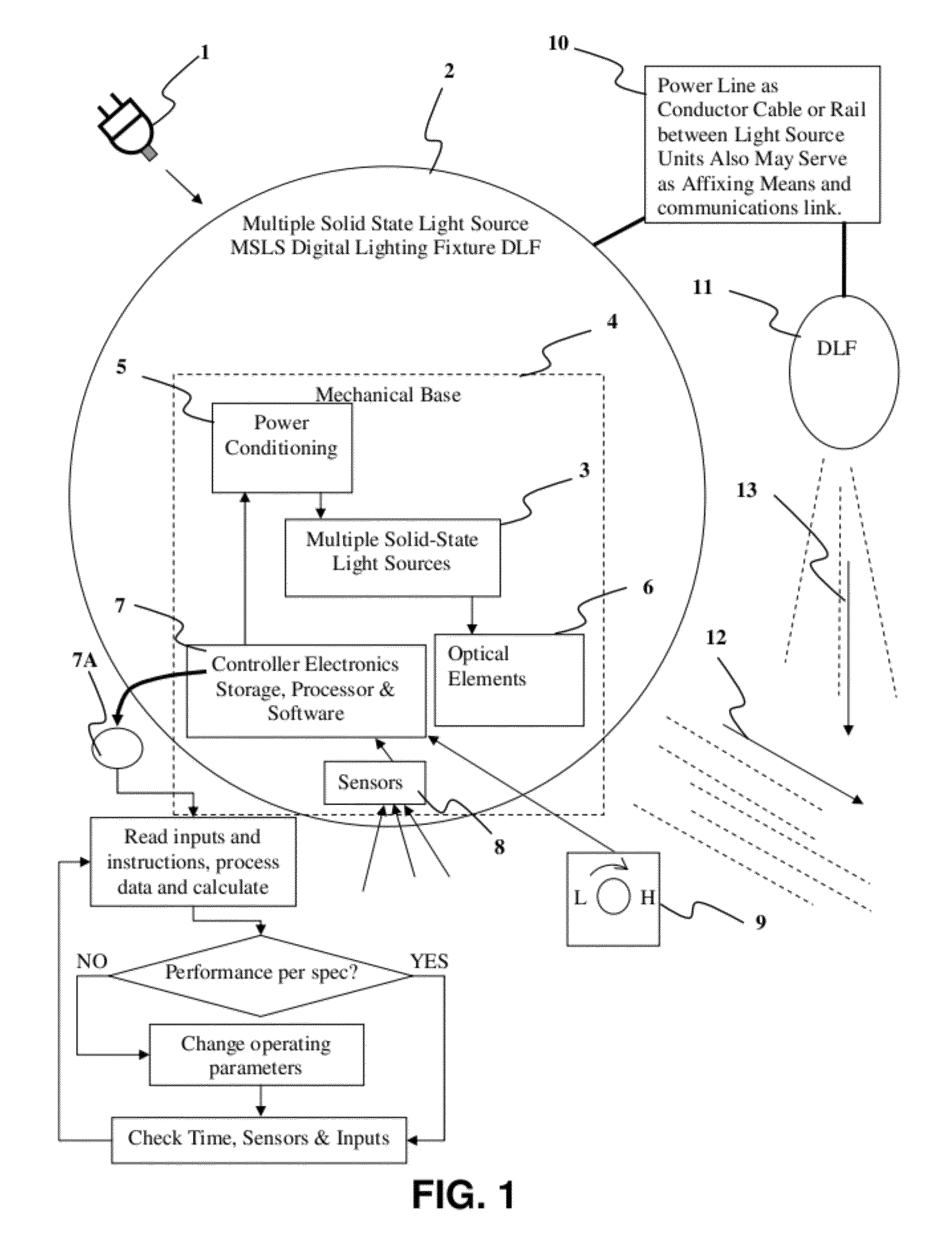
[0278]FIG. 26 is a perspective view of a lighting fixture embodiment 490 capable of producing both a differentiated spatial light intensity distribution as well as a spatially differentiated light spectrum distribution. The luminaire 490 has multiple light source modules 491, 492 and 493 with each module comprised of more than one LED chips which can be powered by the logical controller and control electronics 494 at differentiated power levels. LEDs are arranged in arrays of RGB (substantially red, green and blue color LEDs) or arrays with of any of ROYGBIV LEDs completing white LEDs to produce varieties of white light. The logical controller 494, using algorithms based on the principles of additive color mixing of light sources to control the change in chromacity affects, via the differentiated powering of coincidentally aimed light sources, the production of a unique spectral light distribution having a certain color temperature and / or color rendering index of light. This may be ...


PUM


Abstract

An illuminating device coupled with sensors or an image acquisition device and a logical controller allows illumination intensity and spectrum to be varied according to changing user needs. The system provides illumination to areas according to the principles of correct lighting practice for the optimal performance of visual tasks in the most efficient, cost effective manner. Aspects of the invention include: lighting fixtures which adapt to ambient lighting, movement, visual tasks being performed, and environmental and personal conditions affecting illumination requirements at any given instant. Lighting fixtures having spatial distribution of spectrum and intensity, providing both “background” room lighting, and “task” lighting.

Description

CROSS REFERENCE TO RELATED APPLICATIONS[0001]The present application claims the benefit under 35 U.S.C. .sctn. 119(e) of U.S. Provisional Application No. 60 / 395,308 filed Jul. 12, 2002, entitled: Multiple light source illumination system; and U.S. Provisional Application No. 61 / 535,981, filed Oct. 17, 2011 entitled Adjustable Lighting Fixture, the disclosures of which are all expressly incorporated herein by reference; and this application is a continuation-in-part application of, and claims the benefit under 35 U.S.C. .sctn.120 from, co-pending U.S. patent application Ser. No. 10 / 604,360, entitled “Multiple Light-Source Illuminating System” filed on Jul. 14, 2003, The entire content of this non-provisional patent application is incorporated herein by this reference.BACKGROUND OF THE INVENTIONField of the Invention[0002]The present invention is in the field of radiation producing devices. More particularly, the present invention is in the technical field of lighting fixtures. Howeve...

Claims


Application Information

Patent Timeline
IPC IPC(8): H05B37/02H05B44/00
CPCB60Q1/04F21V29/74B60Q1/1423B60Q2300/054B60Q2300/112B60Q2300/116B60Q2300/122B60Q2300/134B60Q2300/142B60Q2300/21B60Q2300/23B60Q2300/312B60Q2300/314B60Q2300/322B60Q2300/41B60Q2300/42F21K9/13F21K9/135F21S4/008F21S48/10F21V19/02F21V21/02F21V21/30F21V23/0471F21W2101/10F21W2111/023F21W2111/027F21W2111/08F21W2131/103F21W2131/40F21Y2101/02F21Y2113/00H05B33/0812H05B33/0857H05B33/0863H05B37/02F21V23/0464F21V23/0478Y02B20/383Y02B20/343H05B3/008H05B37/0218H05B37/0227B60Q1/085F21S4/28F21K9/23F21K9/232F21Y2115/10F21S41/143F21S41/147F21S41/65H05B45/20H05B47/11H05B47/10H05B47/105F21W2102/30F21W2102/18F21W2102/19F21W2102/13F21S41/153Y02B20/30Y02B20/40H05B47/115A01K1/00B60Q2900/50F21W2102/00H05B45/395
Inventor SPERO, YECHEZKAL EVAN
Owner YECHEZKAL EVAN SPERO
Why Eureka
Try Eureka