Device for reducing speckle effect in a display system

a display system and speckle technology, applied in the field of speckle devices, can solve the problems of generating granular bright and dark patterns called speckles, giving rise to scattering, and more difficult in miniaturizing systems, and achieve the effect of suppressing speckle noise and simple optical systems

Inactive Publication Date: 2012-08-16
HONG KONG APPLIED SCI & TECH RES INST
View PDF3 Cites 22 Cited by
  • Summary
  • Abstract
  • Description
  • Claims
  • Application Information

AI Technical Summary

Benefits of technology

[0017]An object of the present invention is to provide a moving membrane capable of effectively suppressing speckle noise using a simple optical system. The moving membrane vibrates at a higher frequency than the scanning frequency of the scanning mirror, for example, at a frequency which is high enough to generate an enlarged spot before the scanning mirror moves to generate another point in a 2D image. The present invention provides a MEMS (microelectromechanical system) device which has a membrane attached to a stationary frame. The membrane is configured to refract incident laser beams at different refraction angle temporally upon the vibration of the membrane. As each laser beam is refracted to travel in various slightly different paths over time, a larger laser spot size is generated on a plane instead of having one single, coherent laser spot after the laser spot from laser beams travelling along different paths overlap upon arrival on a plane at different time.

Problems solved by technology

When compared with the wavelengths of visible light, the surface of any screen can be regarded as rough and therefore gives rise to scattering.
The reflected light rays reaching a viewer's eyes from various independent scattering areas on the screen surface have relative phase differences and interfere with one another, generating granular bright and dark patterns called speckle.
Some requires an additional component like diffuser to be provided in the system and may make it even more challenging in miniaturizing the systems, for example, a diffuser directing the diffused laser light to a rocking mirror for speckle reduction as described in the U.S. Pat. No. 4,155,630 titled “Speckle Elimination By Random Spatial Phase Modulation”, or a spinning diffuser as described in the U.S. Pat. No. 5,313,479 titled “Speckle-free Display System using Coherent Light”.
Use of additional components may further contribute to difficulties in integrating the speckle reduction scheme into existing systems, while some even require external moving actuators which lead to additional power consumption.
Some proposed solutions require a moving screen which not only makes image display impossible on any still screen but also may become problematic to find an appropriate means to move the screen as the screen size increases.
For example, it will be difficult for the transducer described in the U.S. Pat. No. 5,272,473 entitled “Reduced-Speckle Display System” to work for a large screen where the transducer is required to be coupled to a display screen to set up surface acoustic waves which traverse the display screen.

Method used


Image

  • Device for reducing speckle effect in a display system
  • Device for reducing speckle effect in a display system
  • Device for reducing speckle effect in a display system

Examples


Embodiment Construction

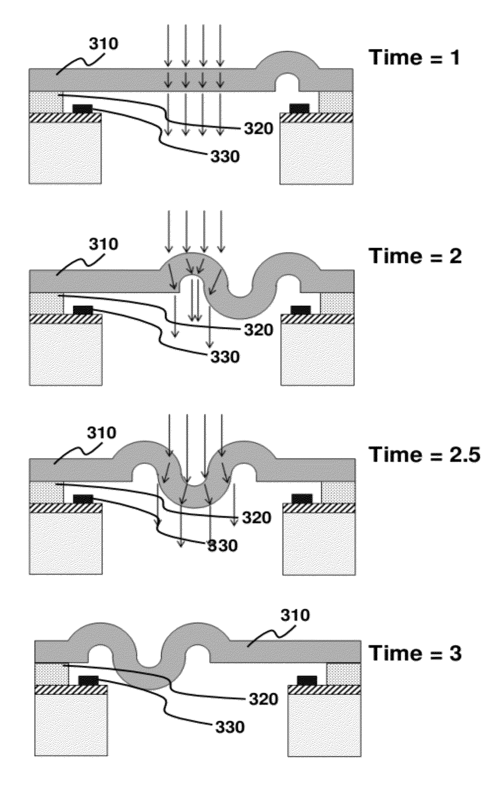
[0048]A MEMS device has at least one movable component. In one embodiment, the movable component is a membrane. The membrane has a certain degree of flexibility allowing the membrane to be deformed and change shapes. The membrane may reflect, refract, polarize or scatter light such as laser beams and may be made of materials such as thin film or conductive film (e.g. ITO).

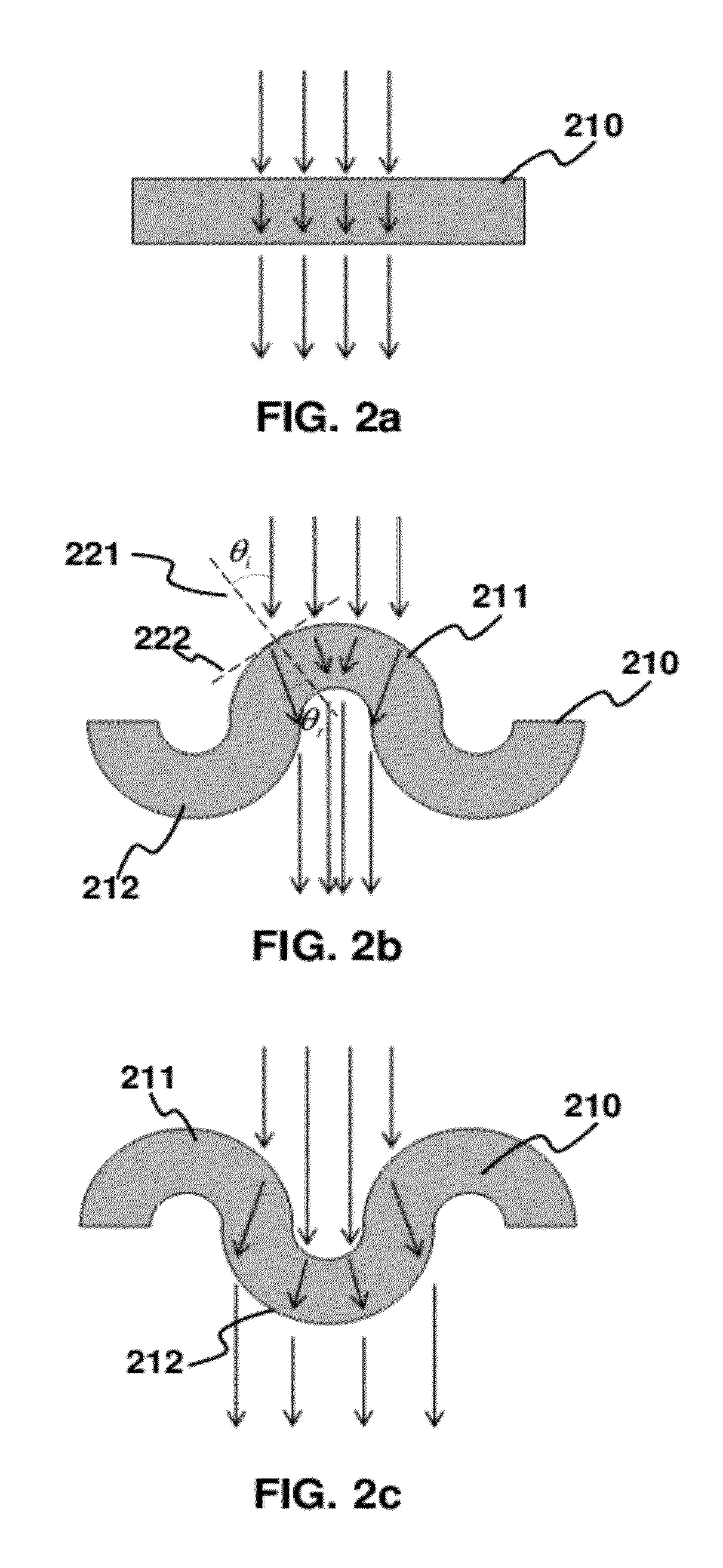
[0049]FIGS. 2a, 2b and 2c depict a transverse wave propagating through a membrane according to one embodiment of the present invention. In this embodiment, light rays such as laser beams travel through the membrane and get refracted.

[0050]According to the Snell's law, the refraction angle θr is given by the following equation (1):

sinθisinθr=ninr(1)

[0051]where θi is the incidence angle, ni is the refractive index of a first medium where an incident ray is travelling before it reaches a second medium with the refractive index nr. The incident ray is refracted by the second medium and travels in the second medium at t...


PUM

PropertyMeasurementUnit
sizeaaaaaaaaaa
refraction anglesaaaaaaaaaa
shapeaaaaaaaaaa

Abstract

The present invention relates to a method and apparatus for speckle noise reduction in laser scanning projection display. In particular, a MEMS device with a vibrating membrane through which light rays are refracted with temporally varying angles is provided for reducing the effect of speckling.

Description

CROSS REFERENCE TO RELATED PATENT APPLICATION[0001]All the subject matter of the co-pending U.S. patent application entitled “Device for Reducing Speckle Effect in a Display System” filed under the attorney docket number P3448US00 on 16 Feb. 2011 and the entire content thereof is hereby incorporated by reference.TECHNICAL FIELD[0002]The present application relates to an apparatus for projecting a digital image in general and, more particularly, to de-speckling devices and methods that can reduce or remove speckle in an image formed by a laser-based projector.BACKGROUND[0003]We receive visual information all the time, for example, watching movies. Nowadays, a huge amount of visual information is generated because of the user-friendliness of consumer electronics such as digital cameras. Similarly, there is a huge demand for displays from which we receive visual information. The development of display technology has been fast and the number of different ways to display an image has bee...

Claims


Application Information

Patent Timeline
Patent Type & Authority Applications(United States)
IPC IPC(8): G02B26/10G02B27/48G02B26/08
CPCG02B26/0833G02B27/48G02B26/101
Inventor CHAN, YICK CHUENLAM, SIU WAIFOK, LO MINGLIU, YINGTSAI, CHEN JUNG
Owner HONG KONG APPLIED SCI & TECH RES INST
Why Eureka
Try Eureka