
Polarizing plate, fabrication method thereof, and display device using the same

a technology of polarizing plate and fabrication method, applied in the field of polarizing plate, can solve problems such as defective image and and achieve the effect of improving the corner light leakage phenomenon

Active Publication Date: 2012-08-16
LG CHEM LTD
View PDF5 Cites 17 Cited by
  • Summary
  • Abstract
  • Description
  • Claims
  • Application Information

AI Technical Summary

Benefits of technology

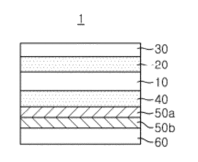
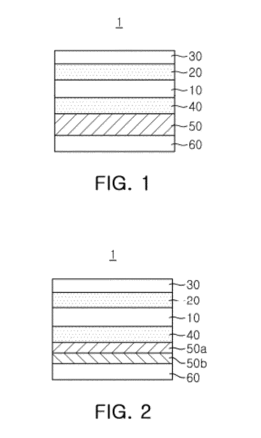
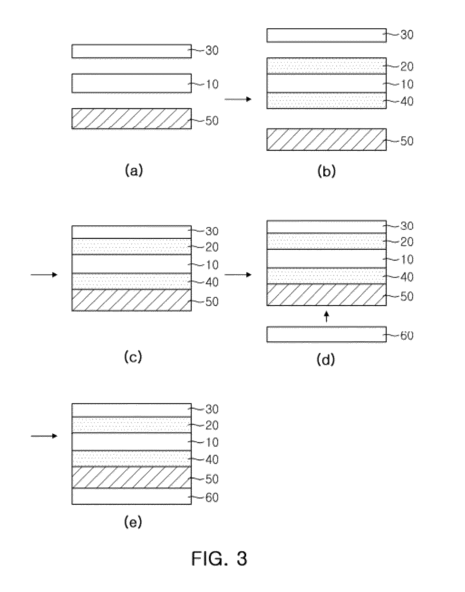
The present invention provides a luminance enhancement film-attached polarizing plate that can improve corner light leakage by controlling the direction of curling generated when the luminance enhancement film is attached. The polarizing plate includes a polarizing element, a first adhesive layer, a second adhesive layer, a protective film, a bonding layer, and a luminance enhancement film. The adhesive layers may be made of PVA-based resin or other types of adhesive resin. The protective film may be made of various polymers. The bonding layer may be made of an acrylic copolymer, epoxy-based resin, polyurethane-based resin, or silicon-based resin. The luminance enhancement film may be a multilayer reflective polarizer, a multilayer reflective film, or a nano-wire grid polarizer. The method for fabricating the polarizing plate involves positioning a protective film and a bonding layer on the polarizing element, interposing adhesive between the protective film and the polarizing element, and between the bonding layer and the polarizing element, and attaching the protective film and the bonding layer to the polarizing element by the medium of the adhesive and drying it. The display device may be a LCD or an organic electroluminescence display.

Problems solved by technology

However, when the luminance enhancement film is attached to the related art polarizing plate, a curling phenomenon (referred to as negative directional curling, hereafter), in which a central surface of the polarizing plate becomes downwardly concave, occurs due to a high shrinkage rate of the luminance enhancement film.
If such negative directional curling occurs on the polarizing film, when a liquid crystal panel is mounted on a module of the LCD, a corner portion of the liquid crystal panel comes off due to the curled polarizing plate so as to be brought into contact with a case, and as a result, a great deal of stress is formed at the corner portion to cause a corner light leakage phenomenon.
Such a corner light leakage phenomenon causes a defective image.

Method used


Image

  • Polarizing plate, fabrication method thereof, and display device using the same
  • Polarizing plate, fabrication method thereof, and display device using the same
  • Polarizing plate, fabrication method thereof, and display device using the same

Examples


embodiment example

[0088]A PVA film (manufactured by Kurary Co. Ltd., polymerization degree:2400) was processed in a rinsing tank and a swelling tank, dyed in an aqueous solution containing I2 and KI, and then, stretched five-fold in an aqueous solution containing boron and Kl to obtain a polarizer.

[0089]And then, a TAC film having a thickness of 60 micrometers was positioned on one surface of the polarizer and a bonding film protected by a PE release film was positioned on the other surface of the polarizer. Here, the bonding film was configured as a bonding layer including two layers having modulus values of 270 MPa and 0.02 MPa, respectively.

[0090]Thereafter, a PVA-based adhesive aqueous solution was put between the polarizer and the TAC film and between the polarizer and the bonding film, attached together by laminator, and then, dried for 8 minutes at 80. And then, the DBEF film to 3M was attached to the bonding film to fabricate the polarizing plate having such a structure as shown in FIG. 2.

experimental example 1

[0092]Curling generation degrees of the polarizing plates fabricated according to Embodiment Example and Comparative Example were measured through naked eyes. FIG. 4 is a photograph obtained by capturing the polarizing plate fabricated according to Embodiment Example of the present invention. FIG. 5 is a photograph obtained by capturing a polarizing plate fabricated according to Comparative Example. In this case, the respective polarizing plates were placed such that the surfaces thereof to which the luminance enhancement film was attached faced downward.

[0093]As shown in FIGS. 4 and 5, it can be seen that, in the case of the polarizing plate according to Comparative Example, the corner portion of the polarizing plate faces in an upward direction, generating negative curling, while in the case of the polarizing plate according to Embodiment Example, the corner portion of the polarizing plate faces in a downward direction, generating positive curling.

experimental example 2

[0094]The polarizing plates fabricated according to Embodiment Example and Comparative Example were mounted in an 17-inch IPS mode LCD monitor and a light leakage phenomenon was observed. FIG. 6 is photograph obtained by capturing the monitor with the polarizing plate according to Embodiment Example attached thereto and the monitor with the polarizing plate according to Comparative Example attached thereto.

[0095]As shown in FIG. 6, it can be seen that the corner light leakage phenomenon was significantly reduced when the polarizing plate according to Embodiment Example was mounted.

[0096]As set forth above, unlike the related art luminance enhancement film-attached polarizing plate, in the luminance enhancement film-attached polarizing plate according to an embodiment of the present invention, since a central surface of the polarizing plate is upwardly convex, generating curling in a positive direction, after the luminance enhancement film is attached, a corner light leakage phenomen...


PUM


Abstract

A polarizing plate, a fabrication method thereof, and a display device using the same are provided. The polarizing plate includes a polarizing element, a first adhesive layer formed on one surface of the polarizing element, a second adhesive layer formed on the other surface of the polarizing element, a protective film attached to an upper portion of the first adhesive layer, a bonding layer attached to a lower portion of the second adhesive layer, and a luminance enhancement film attached to the bonding layer.

Description

CROSS-REFERENCE TO RELATED APPLICATIONS[0001]This application claims the priority of Korean Patent Application No. 2011-0011993 filed on Feb. 10, 2011, in the Korean Intellectual Property Office, the disclosure of which is incorporated herein by reference.BACKGROUND OF THE INVENTION[0002]1. Field of the Invention[0003]The present invention relates to a polarizing plate used in a display device and a fabrication method thereof, and more particularly, to a polarizing plate having an enhanced light leakage which occurs as the polarizing plate is bent when a luminance enhancement film is laminated thereon, and a fabrication method thereof.[0004]2. Description of the Related Art[0005]In general, a polarizing plate is formed by attaching a triacetylcellulose (TAC) film as a protective film to a polarizer in which polyvinyl alcohol (PVA)-based molecule chains are oriented in a certain direction and which have a structure containing an iodine-based compound or a dichroic polarizing material...

Claims


Application Information

Patent Timeline
Patent Type & Authority Applications(United States)
IPC IPC(8): G02B27/28H01J9/20G02B5/30
CPCG02F1/133528G02B5/3033G02F2001/133507Y10T428/1041B32B37/14G02B5/3025G02F2202/28C09K2323/031G02F1/133507Y10T428/31507Y10T428/31511Y10T428/31573Y10T428/31667Y10T428/3175Y10T428/31797Y10T428/31855Y10T428/31909Y10T428/31913Y10T428/3192G02B5/30G02F1/1335
Inventor NAM, SUNG-HYUNKWON, KI-OKRAH, KYUN-II
Owner LG CHEM LTD
Learn More