Green electricity saver model 3000

a technology of green electricity and saver, applied in the integration of power network operation systems, electrical apparatus construction details, climate sustainability, etc., can solve the problems of absorbing the cost of correspondingly larger heat loss in the system, and continuing to operate at uncorrected power factor levels

Inactive Publication Date: 2012-08-16
BOYER ERIC +1
View PDF2 Cites 1 Cited by
  • Summary
  • Abstract
  • Description
  • Claims
  • Application Information

AI Technical Summary

Problems solved by technology

As a result, they generally continue to operate at uncorrected power factor levels, drawing more current than

Method used


Image

  • Green electricity saver model 3000
  • Green electricity saver model 3000
  • Green electricity saver model 3000

Examples


Embodiment Construction

[0016]FIG. 6 schematic of circuit in detail:

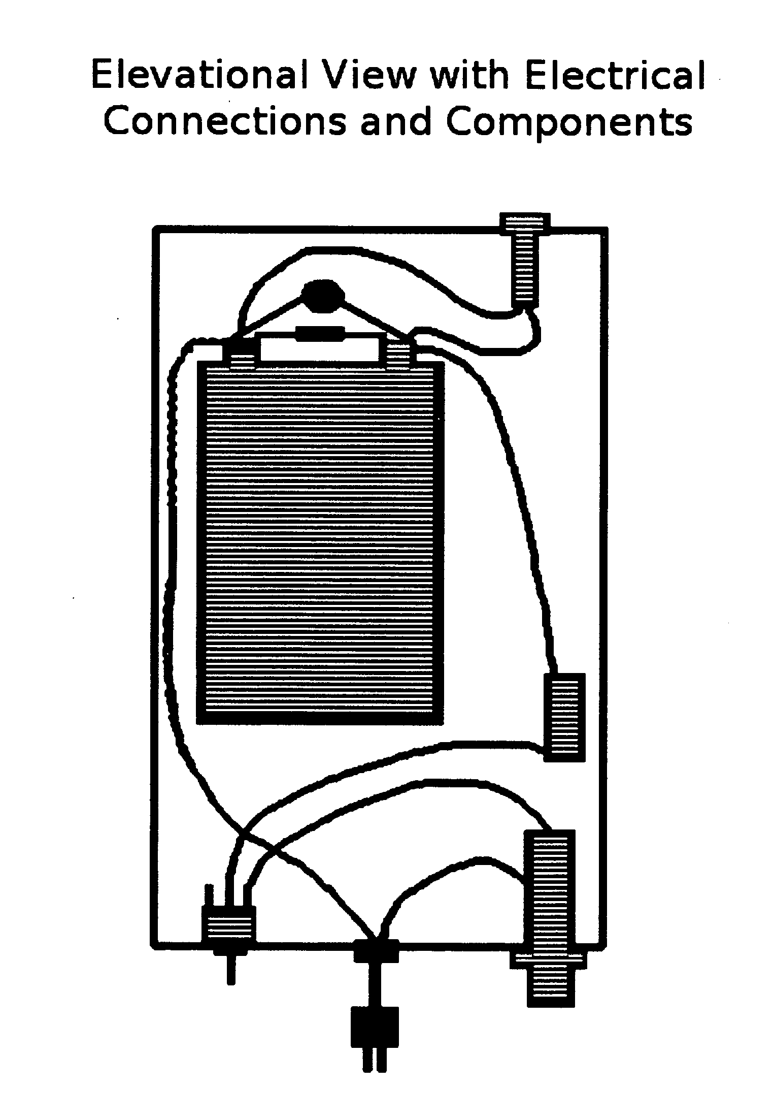
[0017]List of materials with electrical values:[0018]F1—4 amp agc fuse[0019]S1—power switch 5 amp rated[0020]L1—22 micro henry, coil rated 4 amps[0021]C1—10 micro farad capacitor rated at 440 volts[0022]R1—330 kilo ohm resistor rated at 2 watts[0023]V1—240 volt varistor rated at 40 joules[0024]R2—67 kilo ohm ⅛ watt resistor[0025]L2—125 volt neon lamp

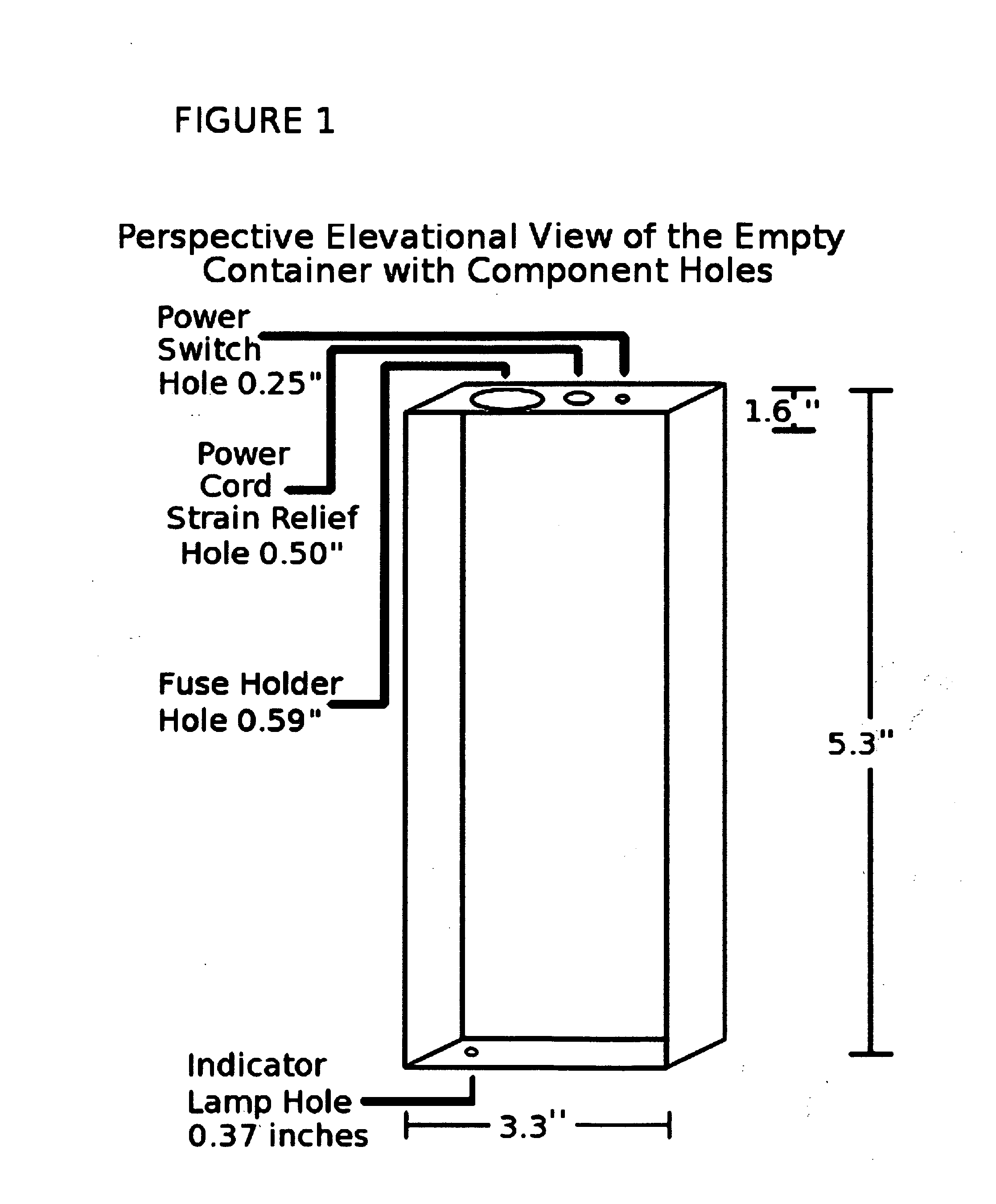
[0026]A two conductor polarized power cord-plug assembly enters the enclosure with strain relief grommet. Conductor one ties to the fuse (F1) assembly. Out of the fuse assembly conductor one enters the power switch (S1), a single pole single through toggle switch. Out of the power switch (S1) conductor one enters the 10 microfarad capacitor (C1) on terminal one of said capacitor. The second electrical conductor from power cord comes through enclosure to the 22 microhenry coil (L1) then second terminal of the 10 microfarad capacitor (C1). From terminal one of 10 microfarad capacitor Across to te...


PUM


Abstract

A universal capacitive power factor corrector usable with single phase inductive loads encases one capacitor, of 10 microfarads, one 240 volt varistor, one 22 microhenry coil, and a 330 k ohm resistor within a housing having a power cord, on off switch, 4 amp fuse, and a indicator lamp. Overall design to correct poorly designed single phase inductive current loads for home or small business.

Description

BACKGROUND OF THE INVENTION[0001]This invention relates generally to energy saving devices and more particularly concerns the reduction of electrical energy demands of smaller or moderate consumers.[0002]More sophisticated electrical energy consumers are well aware of the impact of power factors on power demand. A low plant power factor will require an available capacity much greater then is actually used. Therefore, to avoid premium charges applied to low power factor customers, the large consumer will “correct” its overall power factor by adding to its system a load which draws the opposite kind of reactive power.[0003]Normally, the existing reactive power is inductive, caused by motors, transformers, fluorescent lights and the like, resulting in a lagging kvar (kilovolt amperes reactive). Thus a corrective bank of capacitors is added to the system, providing a leading kvar to balance the system.[0004]The analysis of overall system impedance to determine the corrective load needed...

Claims


Application Information

Patent Timeline
IPC IPC(8): H05K7/02
CPCY02B70/3266Y04S20/242Y02E40/30H02J2003/143H02J3/1821H02J2310/14Y02B70/30Y04S20/222Y02B70/3225
Inventor BOYER, ERICBONO, JOHN
Owner BOYER ERIC
Why Eureka
Try Eureka