
Method and apparatus for controlling a self-refreshing display device coupled to a graphics controller

Inactive Publication Date: 2012-08-16
NVIDIA CORP
View PDF12 Cites 65 Cited by
  • Summary
  • Abstract
  • Description
  • Claims
  • Application Information

AI Technical Summary

Benefits of technology

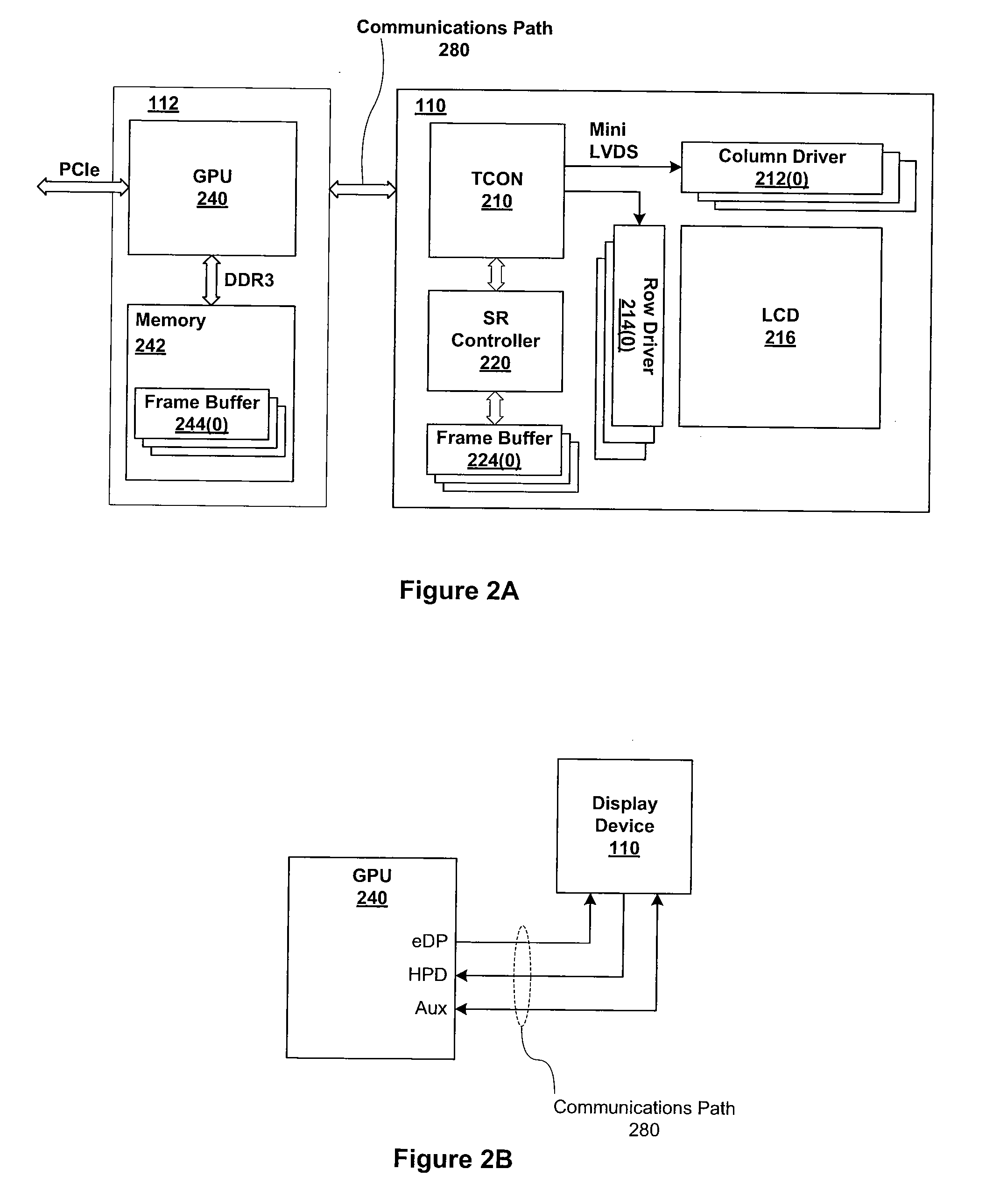
[0009]One embodiment of the present invention sets forth a method for managing the activity level of a graphics processing unit coupled to a display device configured with self-refreshing capability. The method includes the steps of detecting a first level of idleness associated with display data generated by the graphics processing unit, and, in response to detecting the first level of idleness, causing the display device to enter a self-refresh mode, causing the graphics processing unit to stop generating video signals for display on the display device, and causing the graphics processing unit to enter a power-saving state.
[0011]One advantage of the disclosed technique is that the transition of control for generating the video signals used to drive the display device is managed such that the video signals generated by two separate sources are aligned at the point of transition. In so doing, the pixel data represented by the video signals generated by either the graphics controller or the self-refresh controller are consistently displayed at the correct pixel locations of the display device. Consequently, the occurrence of image artifacts in the video frames displayed via the display device is reduced.

Problems solved by technology

One drawback to the approach of driving video signals with two separate controllers is that the video signals generated by the graphics controller may not be synchronized with the video signals generated by the local controller.
The misalignment of the pixel locations may result in image artifacts displayed on the screen when control for driving the video signals used to drive the display device is transitioned between the local controller and the graphics controller.
However, because of the misalignment between the pixel locations associated with the video signals generated by the local controller and the graphics controller during the transition, the pixel locations associated with the video signals used to drive the display device for the second portion of the video frame may not correspond to the pixel locations associated with the second portion of the screen.
Second, the transition of control for generating the video signals used to drive the display device from the local controller to the graphics controller may be delayed until the end of the current video frame such that the display device does not combine video signals from two separate sources into a single video frame.
However, due to the delay in waiting for the video signals generated by the local controller to reach the end of the current frame, the pixel locations associated with the video signals generated by the graphics controller, after the delay, may not correspond to the pixel locations associated with a first, top portion of the screen.
In both of the cases described above, the displayed video frame may include a visible image artifact that is distracting and jarring to a viewer.

Method used


Image

  • Method and apparatus for controlling a self-refreshing display device coupled to a graphics controller
  • Method and apparatus for controlling a self-refreshing display device coupled to a graphics controller
  • Method and apparatus for controlling a self-refreshing display device coupled to a graphics controller

Examples


Embodiment Construction

[0029]In the following description, numerous specific details are set forth to provide a more thorough understanding of the invention. However, it will be apparent to one of skill in the art that the invention may be practiced without one or more of these specific details. In other instances, well-known features have not been described in order to avoid obscuring the invention.

System Overview

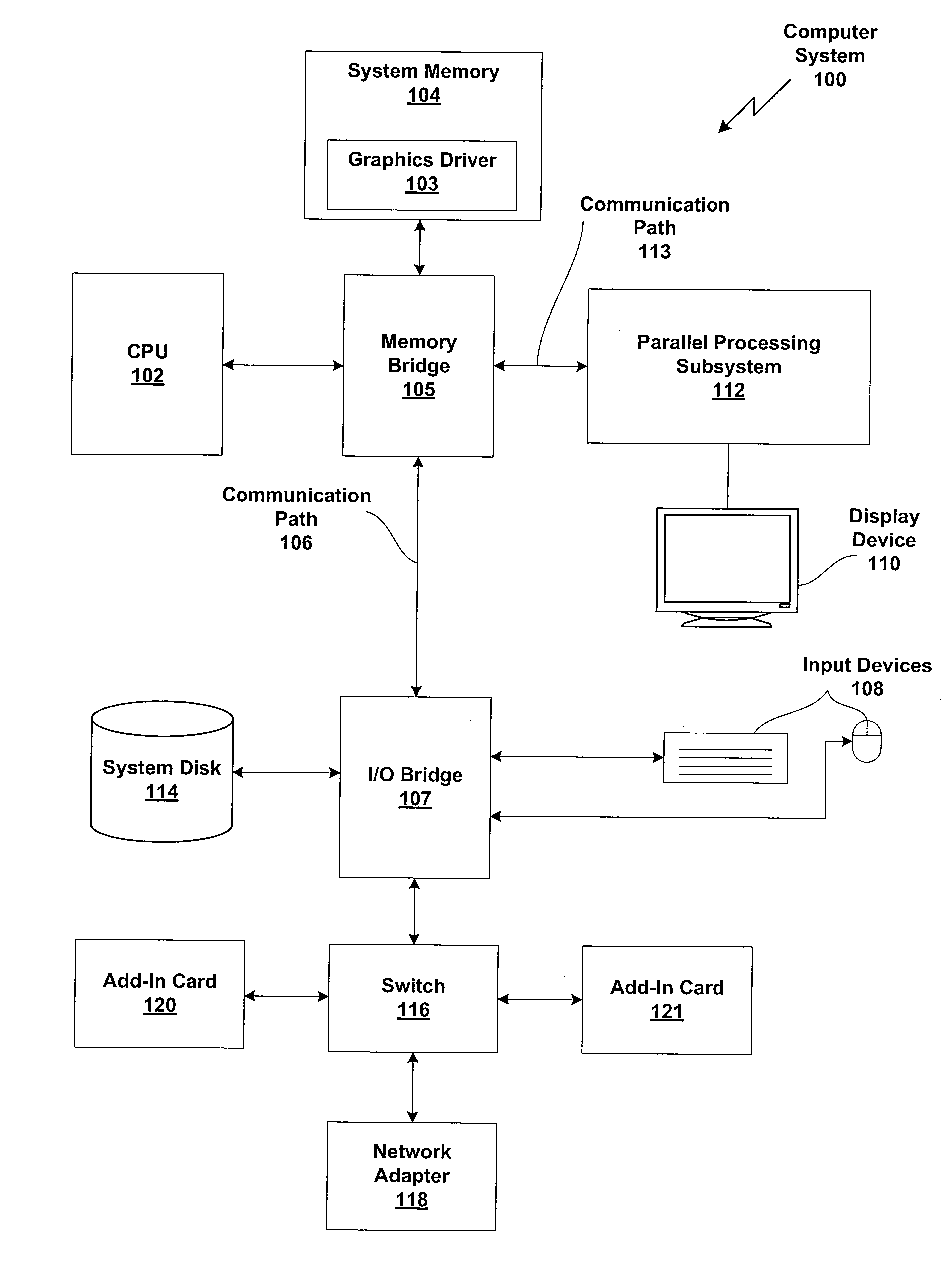
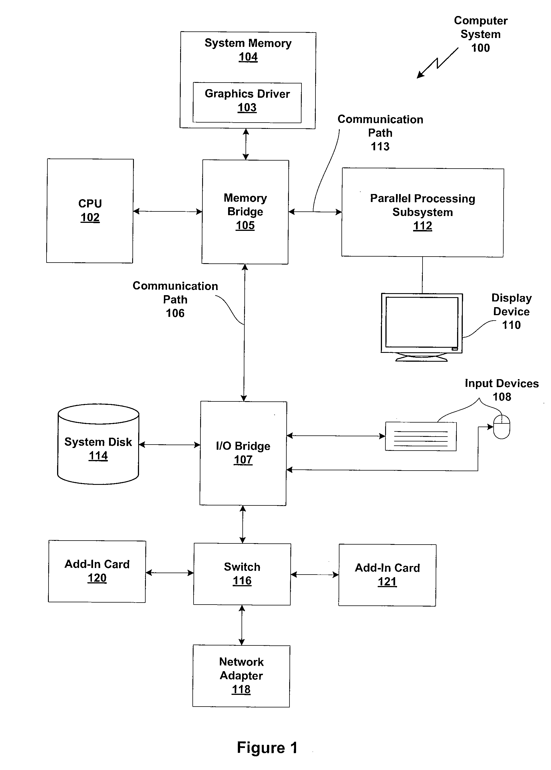
[0030]FIG. 1 is a block diagram illustrating a computer system 100 configured to implement one or more aspects of the present invention. Computer system 100 includes a central processing unit (CPU) 102 and a system memory 104 communicating via an interconnection path that may include a memory bridge 105. Memory bridge 105, which may be, e.g., a Northbridge chip, is connected via a bus or other communication path 106 (e.g., a HyperTransport link) to an I / O (input / output) bridge 107. I / O bridge 107, which may be, e.g., a Southbridge chip, receives user input from one or more user input devices 108...


PUM


Abstract

A method and apparatus for controlling a self-refreshing display device coupled to a graphics controller are disclosed. A self-refreshing display device has a capability to drive the display based on video signals generated from a local frame buffer in the display device. A graphics controller coupled to the display device may optimally be placed in one or more power saving states when the display device is operating in a panel self-refresh mode. The graphics controller detects one or more progressive levels of idleness in the graphics controller and the pixel data stored in a frame buffer. Based on the detected idleness, the graphics controller signals the display device to enter or exit the panel self-refresh mode and enters a power saving state. When exiting the panel self-refresh mode, the display device and / or graphics controller ensure that the video signals generated by the local controller and the graphics controller are aligned.

Description

BACKGROUND OF THE INVENTION[0001]1. Field of the Invention[0002]The invention relates generally to display systems and, more specifically, to a method and apparatus for controlling a self-refreshing display device coupled to a graphics controller.[0003]2. Description of the Related Art[0004]Computer systems typically include some sort of display device, such as a liquid crystal display (LCD) device, coupled to a graphics controller. During normal operation, the graphics controller generates video signals that are transmitted to the display device by scanning-out pixel data from a frame buffer based on timing information generated within the graphics controller. Some recently designed display devices have a self-refresh capability, where the display device includes a local controller configured to generate video signals from a static, cached frame of digital video independently from the graphics controller. When in such a self-refresh mode, the video signals are driven by the local c...

Claims


Application Information

Patent Timeline
IPC IPC(8): H04N17/00H04N7/26H04N13/04
CPCG06F3/14H04N19/597G09G3/003G09G3/2018G09G5/003G09G5/006G09G5/12G09G5/363G09G2320/103G09G2330/021G09G2340/02G09G2360/18G09G2370/04G09G2370/10H04N21/4143H04N21/44016H04N21/44209G06F3/1423
Inventor WYATT, DAVIDOGRINC, MICHAEL A.STEARS, DAVID MATTHEWDEWEY, THOMAS E.MODI, MANISH
Owner NVIDIA CORP
Learn More