Heat Pump Laundry Dryer and a Method for Operating a Heat Pump Laundry Dryer

a technology of heat pump and laundry dryer, which is applied in the direction of laundry driers, lighting and heating equipment, washing machines, etc., can solve the problems of useless drying process cooling capacity, etc., and achieve the effect of shortened transitory phase and faster temperature of air stream

Inactive Publication Date: 2012-08-23
ELECTROLUX HOME PROD CORP NV
View PDF15 Cites 17 Cited by
  • Summary
  • Abstract
  • Description
  • Claims
  • Application Information

AI Technical Summary

Benefits of technology

[0022]Preferably, the first mode occurs during a first operational stage of the laundry dryer starting when the compressor is switched on. Since th...

Problems solved by technology

Thus, the cooling capacity is useless for the drying process.
Further, the cond...

Method used


Image

  • Heat Pump Laundry Dryer and a Method for Operating a Heat Pump Laundry Dryer
  • Heat Pump Laundry Dryer and a Method for Operating a Heat Pump Laundry Dryer
  • Heat Pump Laundry Dryer and a Method for Operating a Heat Pump Laundry Dryer

Examples


first embodiment

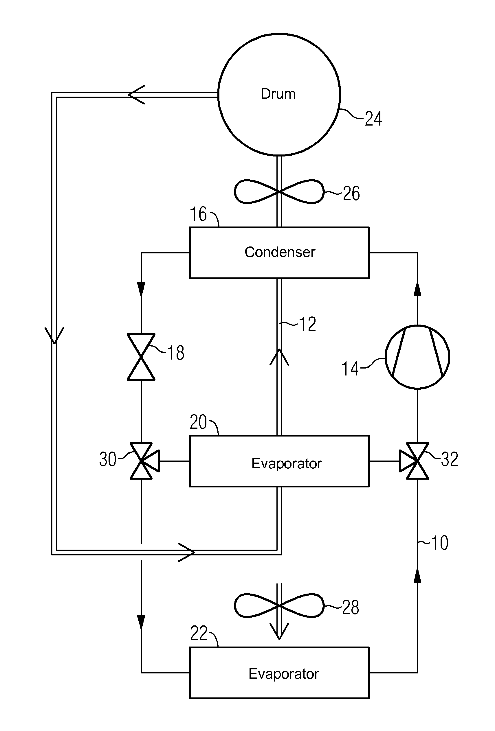
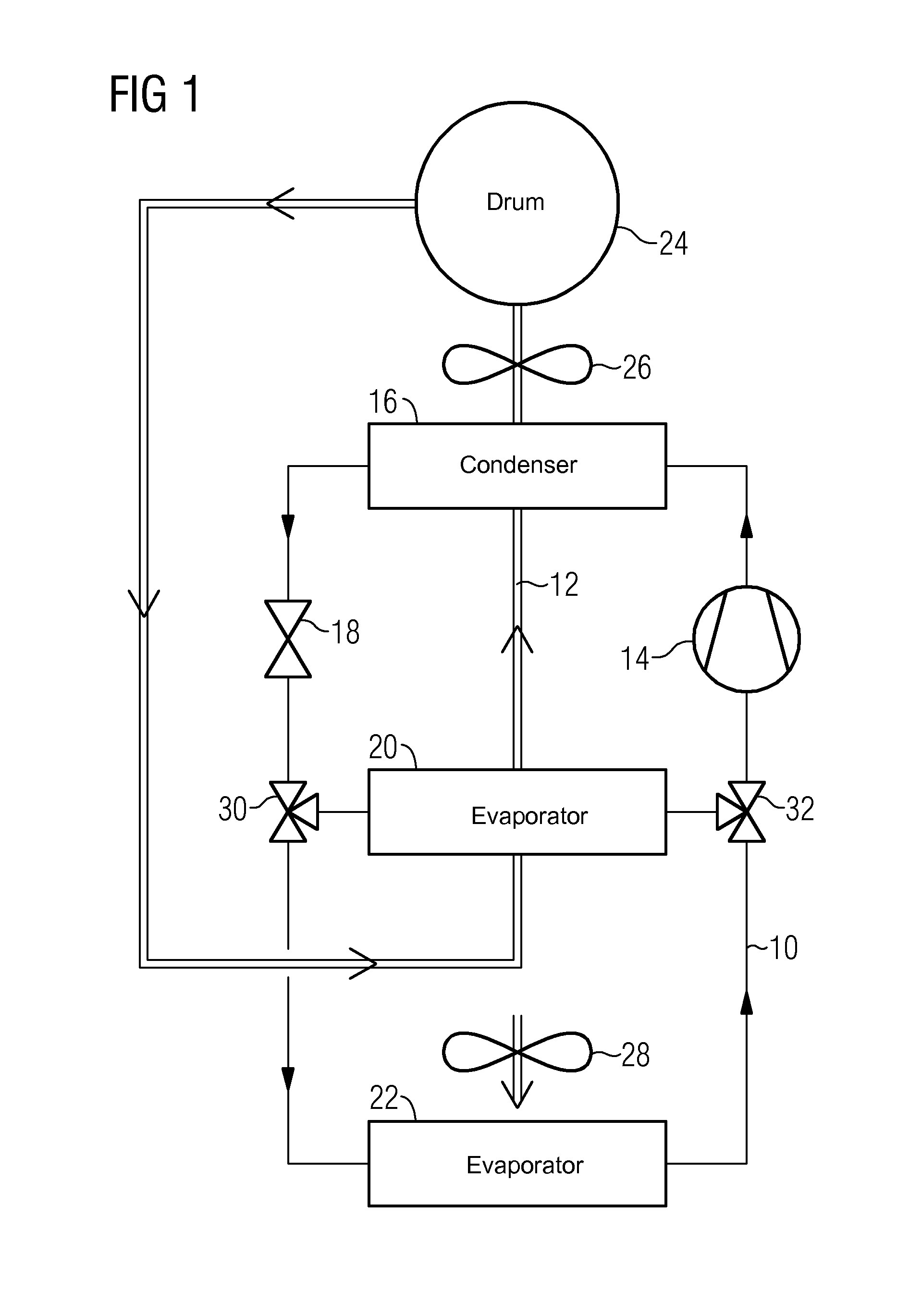
[0028]FIG. 1 illustrates a schematic diagram of a laundry dryer with a heat pump system according to the present invention. The heat pump system includes a closed refrigerant circuit 10 and a drying air circuit 12, preferably, forming a closed loop circuit.

[0029]The drying air circuit 12 includes a laundry chamber 24, preferably a rotatable drum, a main evaporator 20, a condenser 16 and a fan 26. The condenser 16 and the main evaporator 20 are heat exchangers and form the thermal interconnections between the refrigerant circuit 10 and the drying air circuit 12.

[0030]The refrigerant circuit 10 includes a compressor 14, the condenser 16, an expansion device 18, the main evaporator 20, an additional evaporator 22 and an additional fan 28. The compressor 14, the condenser 16, the expansion device 18 and the main evaporator 20 are arranged in series and form a closed loop. The additional evaporator 22 is arranged parallel to the evaporator 20. Instead of the main evaporator 20, the addit...
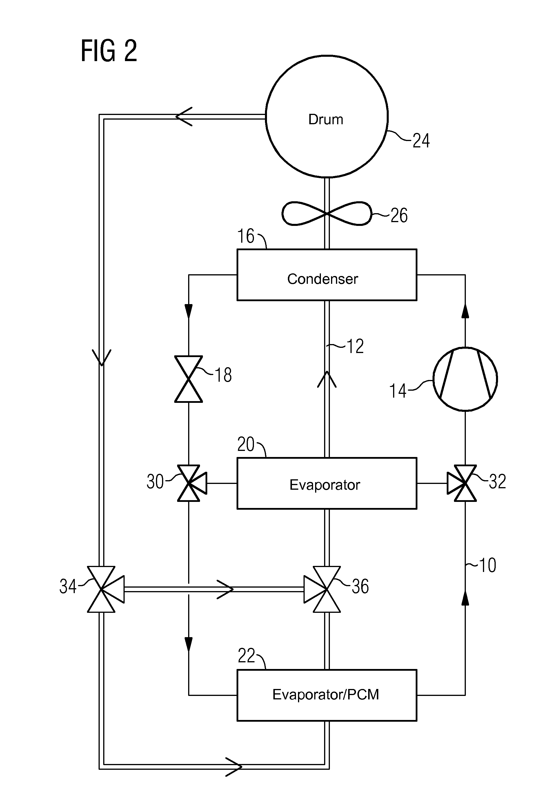
second embodiment

[0042]Further, the heat pump system of the second embodiment includes a first baffle device 34 and a second baffle device 36, so that the air stream flows either through the main evaporator 20 or through the additional evaporator 22. In the latter case, the additional evaporator 22 is a heat exchanger forming a thermal interconnection between the refrigerant circuit 10 and the air stream circuit 12.

[0043]In the second embodiment, phase change materials are used as a cold sink for the additional evaporator 22. At least a part of the refrigerant circuit is embedded in an assembly of known suitable phase change materials (PSMs). During the transitory phase, the phase change materials are used as a cooling source for the heat pump operation, wherein the drying air forms the heating source. The refrigerant cools down the phase change materials, which become solidified, wherein the refrigerant is heated up and vaporized. The phase change materials are set / selected to change phase at a con...


PUM


Abstract

A heat pump system of a laundry dryer comprises a closed refrigerant circuit (10) and a drying air circuit (12). The refrigerant circuit (10) includes a compressor (14), a condenser (16), an expansion device (18) and a main evaporator (20). The air stream circuit includes the main evaporator (20), the condenser (16), a laundry drum and at least one fan (26). The refrigerant circuit (10) and the air stream circuit are thermally coupled by the condenser (16) and the main evaporator (20). The condenser (18) is a heat exchanger provided for heating up the air stream and cooling down the refrigerant. The main evaporator (20) is a heat exchanger provided for cooling down the air stream and heating up the refrigerant. At least one additional evaporator (22) is arranged in parallel to the main evaporator (20), and is switchably connected to the refrigerant circuit (10).

Description

CROSS-REFERENCE TO RELATED APPLICATION[0001]This application claims priority to European Application No. 11155063.8, filed Feb. 18, 2011.BACKGROUND OF THE INVENTION[0002]The present invention relates to a laundry dryer with a heat pump system. Further, the present invention relates to a method for operating a laundry dryer with a heat pump system.[0003]In laundry dryers, heat pump technology is the most efficient way to save energy during drying laundry. In conventional heat pump laundry dryers, a drying air stream flows in a closed loop. The drying air stream is moved by a fan, passes a laundry drum and removes water from wet clothes. Then the drying air stream is cooled down and dehumidified in a heat pump evaporator, heated up in a heat pump condenser and directed again into the laundry drum.[0004]A refrigerant is compressed by a compressor, condensed in the condenser, expanded in an expansion device and then vaporized in the evaporator. Therefore, the temperatures of the drying ...

Claims


Application Information

Patent Timeline
IPC IPC(8): F26B21/00F26B3/02
CPCD06F58/206
Inventor BISON, ALBERTOCAVARRETTA, FRANCESCO
Owner ELECTROLUX HOME PROD CORP NV
Why Eureka
Try Eureka