Process for hydrotreating naphtha fraction and process for producing hydrocarbon oil

a naphtha fraction and hydrotreating reactor technology, applied in the direction of hydrocarbon oil treatment, hydrocarbon oil treatment, refining to change the hydrocarbon structural skeleton, etc., can solve the problems of undesirable inclusion of naphtha fractions in liquid fuel products, excessive temperature increase in naphtha fraction hydrotreating reactors, etc., and achieve the effect of producing effective and simple process

Inactive Publication Date: 2012-08-23
JAPAN OIL GAS & METALS NAT CORP +5
View PDF1 Cites 7 Cited by
  • Summary
  • Abstract
  • Description
  • Claims
  • Application Information

AI Technical Summary

Benefits of technology

[0019]According to the present invention, the degree of progression of a naphtha fraction hydrotreating step can be ascertained without analyzing the treated naphtha fraction and the raw naphtha fraction, and by adjusting the hydrotreating reaction temperature based on the ascertained degree of progression, the naphtha fraction hydrotreating step can be controlled appropriately and rapidly via a simple process. Furthermore, a hydrocarbon oil of naphtha fraction can be produced effectively.

Problems solved by technology

These by-products are impurities, and their inclusion within the liquid fuel products is undesirable.
Because these reactions are highly exothermic, excessive temperature increase in the naphtha fraction hydrotreating reactor is a concern.

Method used


Image

  • Process for hydrotreating naphtha fraction and process for producing hydrocarbon oil
  • Process for hydrotreating naphtha fraction and process for producing hydrocarbon oil

Examples


Embodiment Construction

[0023]First is a description of an example of a liquid fuel synthesizing system and a process for producing liquid fuel base stocks using the system to which the process for hydrotreating a naphtha fraction and process for producing a hydrocarbon oil according to the present invention may be applied to perform the GTL Technology.

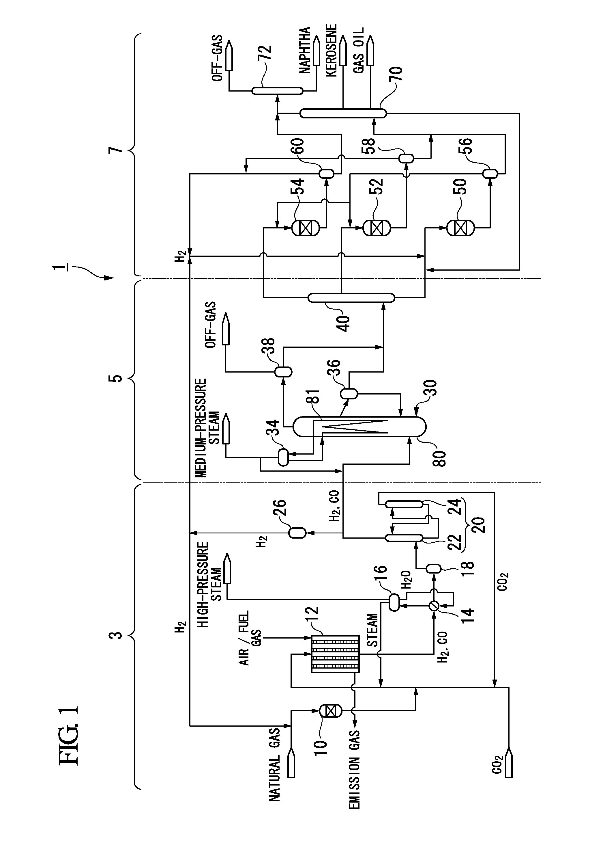
[0024]FIG. 1 illustrates an example of a liquid fuel synthesizing system for performing the GTL Technology.

[0025]This liquid fuel synthesizing system 1 includes a synthesis gas production unit 3, an FT synthesis unit 5, and an upgrading unit 7. In the synthesis gas production unit 3, a natural gas that functions as a hydrocarbon feedstock is reformed to produce a synthesis gas containing carbon monoxide gas and hydrogen gas. In the FT synthesis unit 5, hydrocarbon compounds are synthesized from the synthesis gas produced in the synthesis gas production unit 3 via an FT synthesis reaction. In the upgrading unit 7, the hydrocarbon compounds synthesized in the ...


PUM

PropertyMeasurementUnit
temperatureaaaaaaaaaa
boiling pointaaaaaaaaaa
reaction temperatureaaaaaaaaaa

Abstract

A process for hydrotreating a naphtha fraction that includes a step of estimating the difference between the naphtha fraction hydrotreating reactor outlet temperature and inlet temperature, based on the reaction temperature of the Fischer-Tropsch synthesis reaction and the ratio of the flow rate of the treated naphtha fraction returned to the naphtha fraction hydrotreating step relative to the flow rate of the treated naphtha fraction discharged from the naphtha fraction hydrotreating step, a step of measuring the difference between the naphtha fraction hydrotreating reactor outlet temperature and inlet temperature, and a step of adjusting the reaction temperature of the naphtha fraction hydrotreating step so that the measured difference between the naphtha fraction hydrotreating reactor outlet temperature and inlet temperature becomes substantially equal to the estimated difference between the naphtha fraction hydrotreating reactor outlet temperature and inlet temperature.

Description

TECHNICAL FIELD[0001]The present invention relates to a process for hydrotreating a naphtha fraction contained within hydrocarbon compounds produced by a Fischer-Tropsch synthesis reaction, and also relates to a process for producing a hydrocarbon oil.[0002]Priority is claimed on Japanese Patent Application No. 2009-254916, filed Nov. 6, 2009, the content of which is incorporated herein by reference.BACKGROUND ART[0003]As a process for producing hydrocarbons that can be used as feedstocks for liquid fuel products such as naphtha (raw gasoline), kerosene and gas oil, a process that employs a Fischer-Tropsch synthesis reaction (hereafter abbreviated as “FT synthesis reaction”) which uses carbon monoxide gas (CO) and hydrogen gas (H2) as a feedstock is already known.[0004]Further, as a technology for producing liquid fuel base stocks from a gaseous hydrocarbon such as natural gas using the FT synthesis reaction, GTL (Gas To Liquids) Technology has been known. In this GTL Technology, a ...

Claims


Application Information

Patent Timeline
Patent Type & Authority Applications(United States)
IPC IPC(8): C10G45/00
CPCC10G2/30C10G45/02C10G45/72C10G2300/1022C10G2300/1044C10G2300/202C10G2400/02C10G2/32C10G45/58C10G45/32C10G2300/4081C10G2300/4006
Inventor TASAKA, KAZUHIKOTANAKA, YUICHIIWAMA, MARIE
Owner JAPAN OIL GAS & METALS NAT CORP
Why Eureka
Try Eureka