Lighting device and illumination apparatus including same

a technology of illumination apparatus and light source, which is applied in the direction of lighting apparatus, electroluminescent light sources, light sources, etc., can solve the problems that the light source may stop the intermittent operation of the light source, and achieve the effect of preventing a concentrated current, reducing power loss, and simple configuration

Active Publication Date: 2012-08-23
PANASONIC INTELLECTUAL PROPERTY MANAGEMENT CO LTD
View PDF2 Cites 58 Cited by
  • Summary
  • Abstract
  • Description
  • Claims
  • Application Information

AI Technical Summary

Benefits of technology

[0015]In accordance with the present invention, it is possible to reduce power loss by a simple configuration, and to prevent a concentrated current from flowing through normally operating light emitting modules when there develops an abnormality in the load.

Problems solved by technology

Further, if the abnormality detector detects the abnormality in the load, the lighting unit may perform an intermittent operation for intermittently reducing the current being supplied to the load, and if the abnormality detector is switched from a state in which the abnormality in the load is detected to a state in which the abnormality in the load is not detected while the lighting unit performs the intermittent operation, the lighting unit may stop the intermittent operation.

Method used


Image

  • Lighting device and illumination apparatus including same
  • Lighting device and illumination apparatus including same
  • Lighting device and illumination apparatus including same

Examples


first embodiment

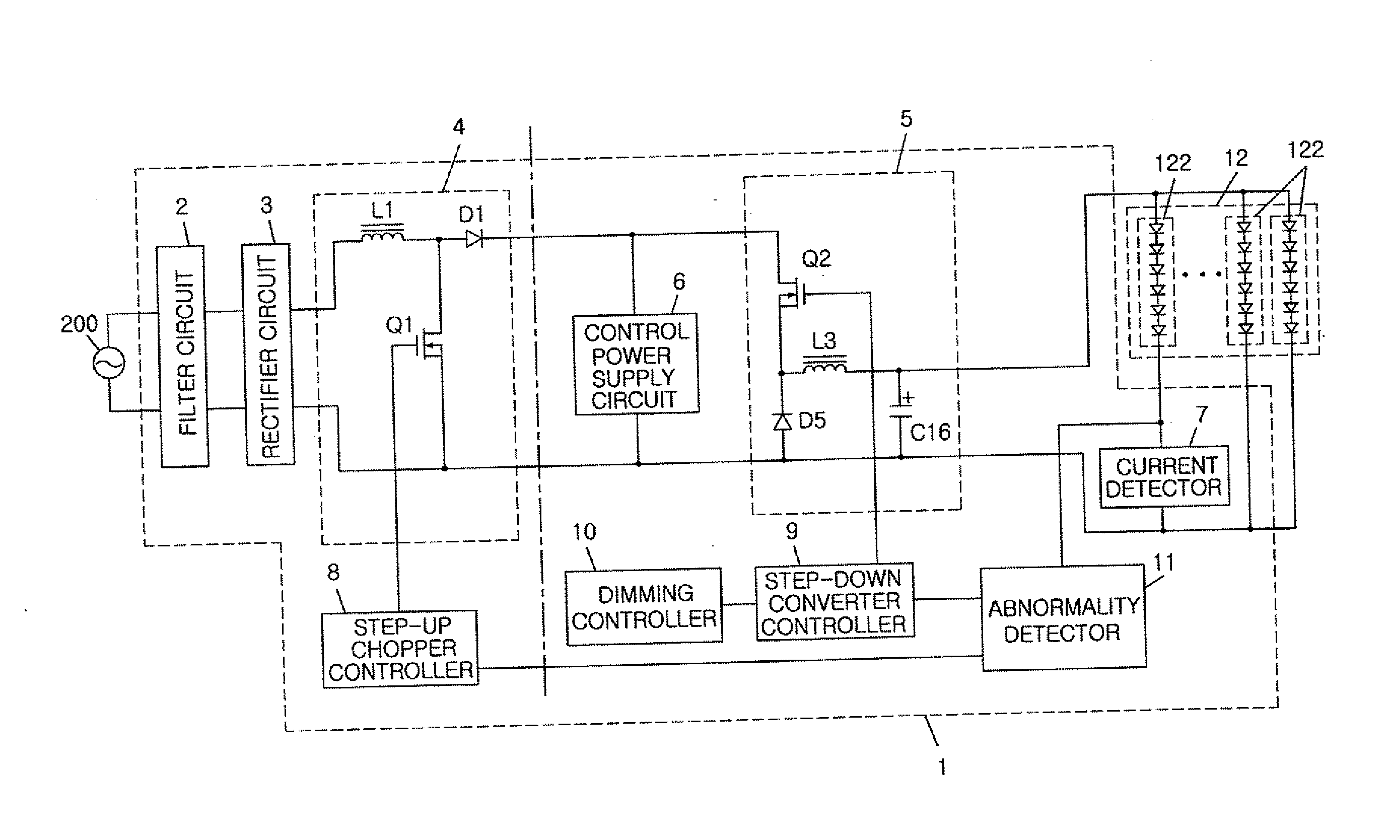
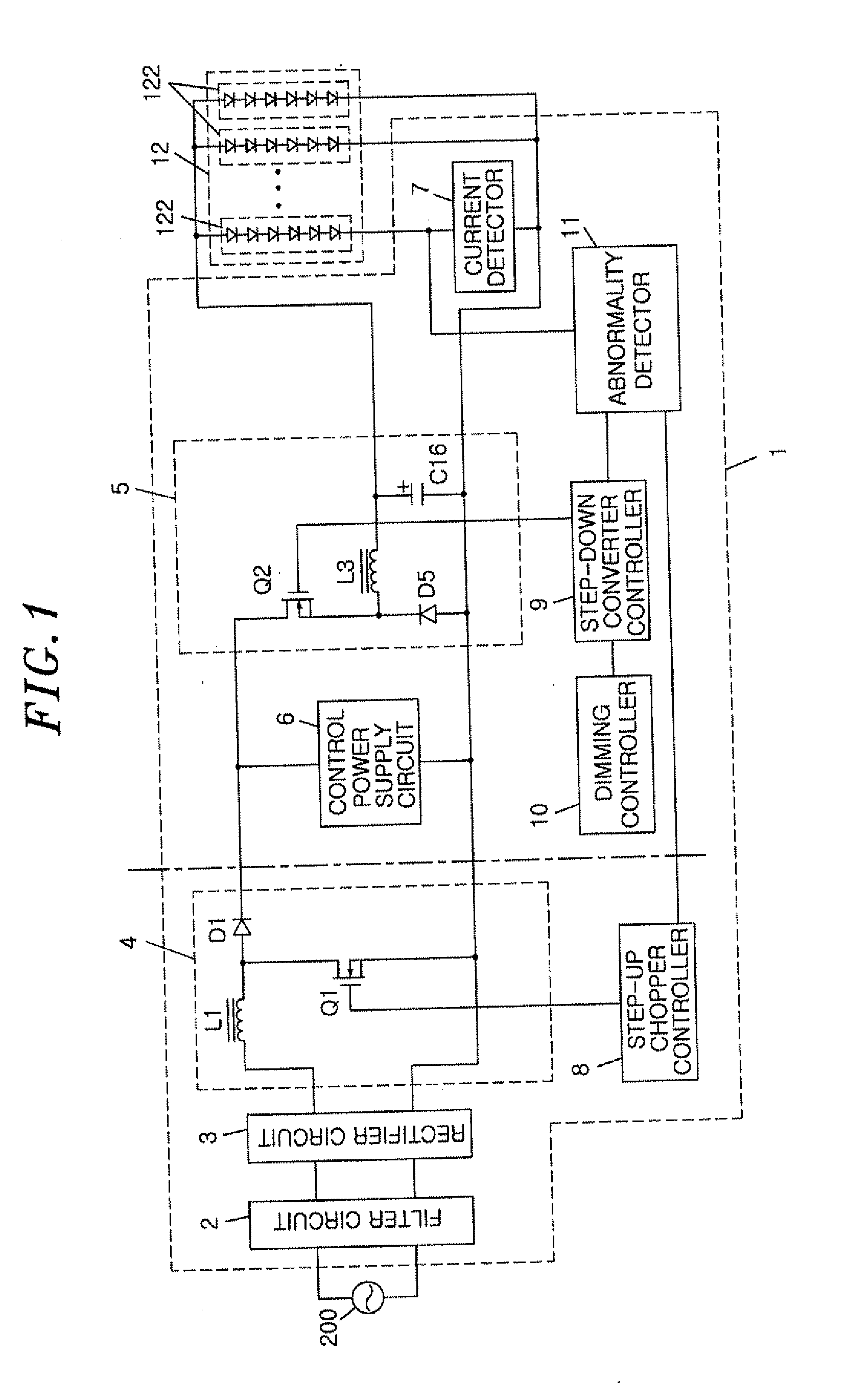
[0025]FIG. 1 illustrates a block diagram showing a configuration of a lighting device 1 in accordance with a first embodiment of the present invention. The lighting device 1 of this embodiment includes a filter circuit 2, a rectifier circuit 3, a step-up chopper circuit 4, a step-down converter 5, a control power supply circuit 6, a current detector 7, a step-up chopper controller 8, a step-down converter controller 9, a dimming controller 10, and an abnormality detector 11.

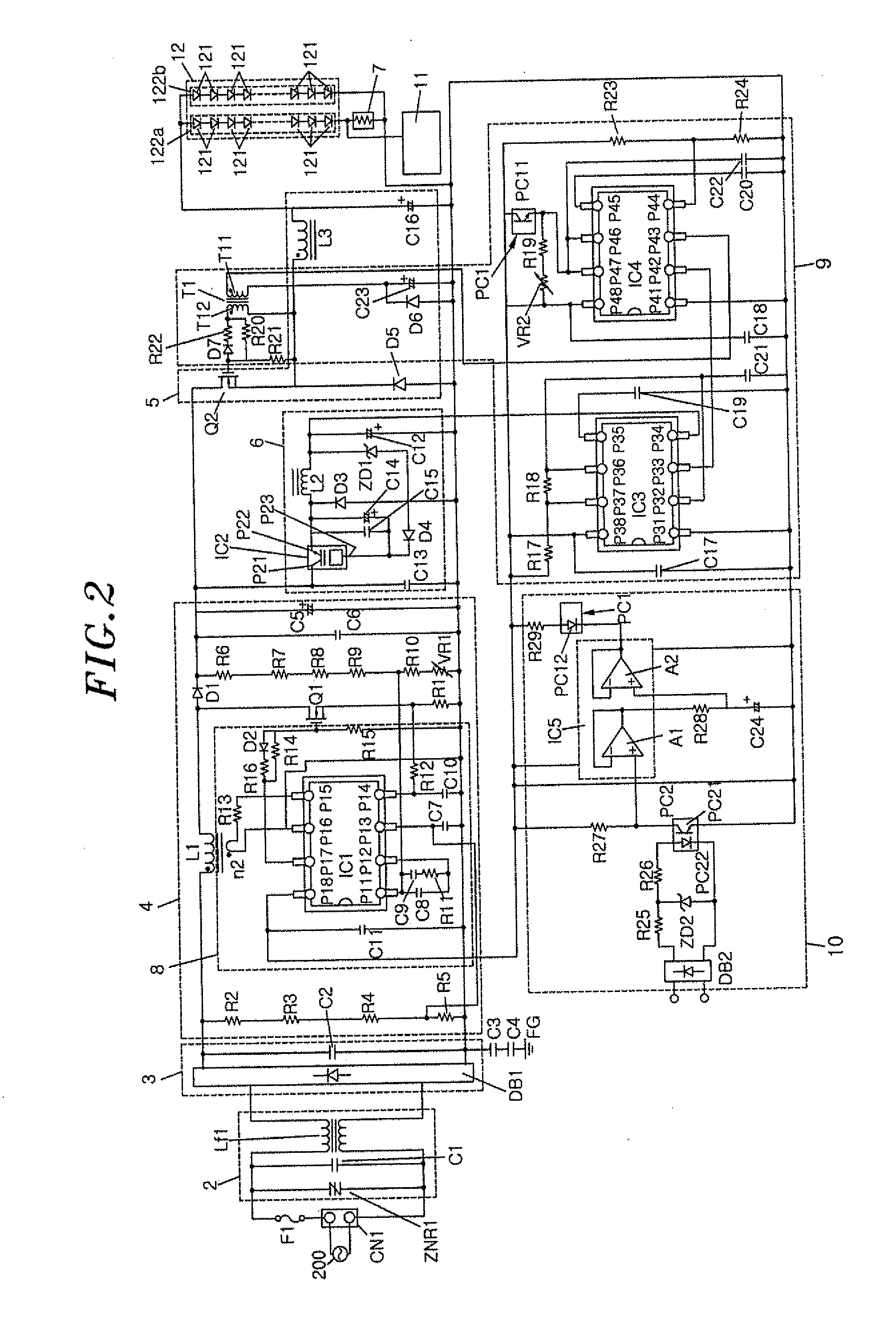
[0026]Each part of the lighting device 1 of this embodiment will be described with reference to a circuit diagram shown in FIG. 2.

[0027]A commercial AC power source 200 (e.g., 100 V, 50 / 60 Hz) is connected between input terminals of the filter circuit 2 via a connector CN1. A fuse F1 is provided between the connector CN1 and the filter circuit 2. A parallel circuit of a varistor (surge voltage protection element) ZNR1 and a filter capacitor C1 is connected between the input terminals of the filter circuit 2. A co...

second embodiment

[0139]FIG. 6 illustrates a block diagram of the lighting device 1 in accordance with a second embodiment of the present invention. The lighting device 1 of this embodiment includes a timer circuit 13. The like reference numerals will be given to the like parts as those in the first embodiment, and redundant description thereof will be omitted. Further, in this embodiment, the filter circuit 2, the rectifier circuit 3, the step-up chopper circuit 4, the step-down converter 5, the control power supply circuit 6, the step-up chopper controller 8, the step-down converter controller 9, the dimming controller 10 and the timer circuit 13 correspond to a lighting unit described in the claims.

[0140]The timer circuit 13 alternately and repeatedly blocks and unblocks the output of the abnormality detector 11 when it is determined that the load 12 is in an abnormal state based on the output of the abnormality detector 11. For example, a case where the abnormality detector 11 is configured as sh...

third embodiment

[0147]FIG. 7 illustrates an external appearance of an illumination apparatus in accordance with a third embodiment of the present invention. In this illumination apparatus, the lighting device 1 is separately provided from an LED unit 14.

[0148]The LED unit 14 is configured such that a substrate 142 in which the load 12 having a plurality of the LED modules 122 is mounted is contained in a metal cylindrical housing 141 having an open side, and the open side of the housing 141 is covered with a light diffusion plate 143. The light emitted from the LED modules 122 is irradiated to the outside after being diffused and transmitted through the light diffusion plate 143. The LED unit 14 is embedded in a ceiling panel 15 such that the light diffusion plate 143 is exposed downward from the surface of the ceiling panel 15.

[0149]The lighting device 1 is disposed on the rear surface of the ceiling panel 15. The step-down converter 5 is connected to the LED unit 14 through a lead line 16 and a c...


PUM


Abstract

A lighting device includes a lighting unit which controls a current being supplied to a load, in which light emitting modules, each having one or more semiconductor light emitting elements connected in series, are connected in parallel, to be a constant current; a current detector which detects a current flowing through one of the light emitting modules; and an abnormality detector which compares a detected value from the current detector with an upper limit and a lower limit of a predetermined current range to detect an abnormality in the load. The abnormality detector detects the abnormality in the load if the detected value from the current detector is larger than the upper limit or smaller than the lower limit, and if the abnormality in the load is detected, the lighting unit reduces the current being supplied to the load.

Description

FIELD OF THE INVENTION[0001]The present invention relates to a lighting device and an illumination apparatus including same.BACKGROUND OF THE INVENTION[0002]Recently, there is an increasing consumer interest in illumination and an illumination apparatus using light emitting diodes (LED elements) as light sources are being diversified. Under these circumstances, there is an increasing number of high-power products and the like in which LED modules, each having multiple LED elements connected in series to each other, are connected in parallel. Further, in order to cope with the wide variability of LEDs, a constant current circuit for supplying a constant current may be provided in the LED modules connected in parallel.[0003]However, in a case where the LED modules are connected in parallel, if some of the LED modules are detached or an open-circuit mode failure occurs therein, there may flow concentrated currents through the other LED modules, and it may lead to destruction and degrad...

Claims


Application Information

Patent Timeline
Patent Type & Authority Applications(United States)
IPC IPC(8): H05B37/02H05B44/00
CPCH05B33/089H05B45/52
Inventor ESAKI, SANAHIRAMATU, AKINORI
Owner PANASONIC INTELLECTUAL PROPERTY MANAGEMENT CO LTD
Why Eureka
Try Eureka