Surface acoustic wave resonator, surface acoustic wave oscillator, and electronic instrument

a surface acoustic wave and oscillator technology, applied in piezoelectric/electrostrictive/magnetostrictive devices, oscillator generators, electrostatic generators/motors, etc., can solve the problem of not being able to find cut angle substrates with temperature characteristics, and achieve high reflection coefficient

Active Publication Date: 2012-08-23
SEIKO EPSON CORP
View PDF0 Cites 15 Cited by
  • Summary
  • Abstract
  • Description
  • Claims
  • Application Information

AI Technical Summary

Benefits of technology

[0018]According to the surface acoustic wave resonator with these kinds of characteristic, it is possible to realize an exhibition of good frequency-temperature characteristics in an operating temperature range. Also, by having these kinds of characteristic, it is possible to suppress the deterioration of environmental resistance characteristics accompanying an increase in the electrode film thickness.APPLICATION EXAMPLE 4

Problems solved by technology

Also, in Japanese Patent No. 3,851,336, as well as describing a configuration for making a curve indicating the frequency-temperature characteristics a tertiary curve in a SAW device using an LST cut quartz crystal substrate, it is described that, in a SAW device using a Rayleigh wave, it has not been possible to find a cut angle substrate having the kind of temperature characteristics indicated by a tertiary curve.

Method used


Image

  • Surface acoustic wave resonator, surface acoustic wave oscillator, and electronic instrument
  • Surface acoustic wave resonator, surface acoustic wave oscillator, and electronic instrument
  • Surface acoustic wave resonator, surface acoustic wave oscillator, and electronic instrument

Examples


application example 2

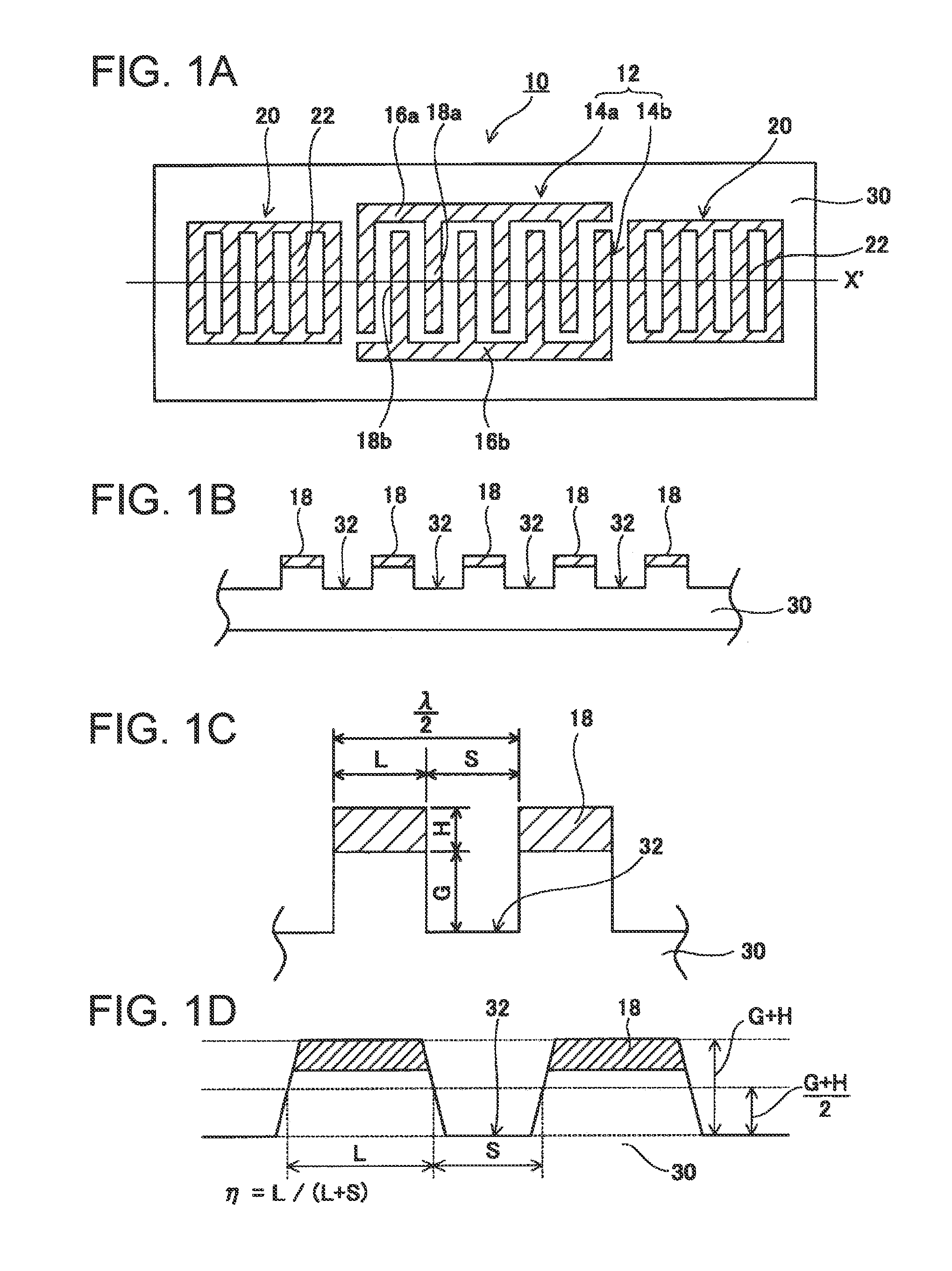
[0015]With the surface acoustic wave resonator according to application example 1, the inter-electrode finger groove depth G satisfies the relationship of

[Expression 4]

0.01λ≦G≦−0.0695λ  (3)

[0016]According to the surface acoustic wave resonator with these kinds of characteristic, even in the event that the depth G of the inter-electrode finger grooves deviates due to manufacturing error, it is possible to keep the shift of resonance frequency between individual resonators within a correctable range.

application example 3

[0017]With the surface acoustic wave resonator according to application example 1 or 2, when the electrode film thickness of the IDT is H, H satisfies the relationship of

[Expression 5]

0<H≦0.035λ  (7)

[0018]According to the surface acoustic wave resonator with these kinds of characteristic, it is possible to realize an exhibition of good frequency-temperature characteristics in an operating temperature range. Also, by having these kinds of characteristic, it is possible to suppress the deterioration of environmental resistance characteristics accompanying an increase in the electrode film thickness.

application example 4

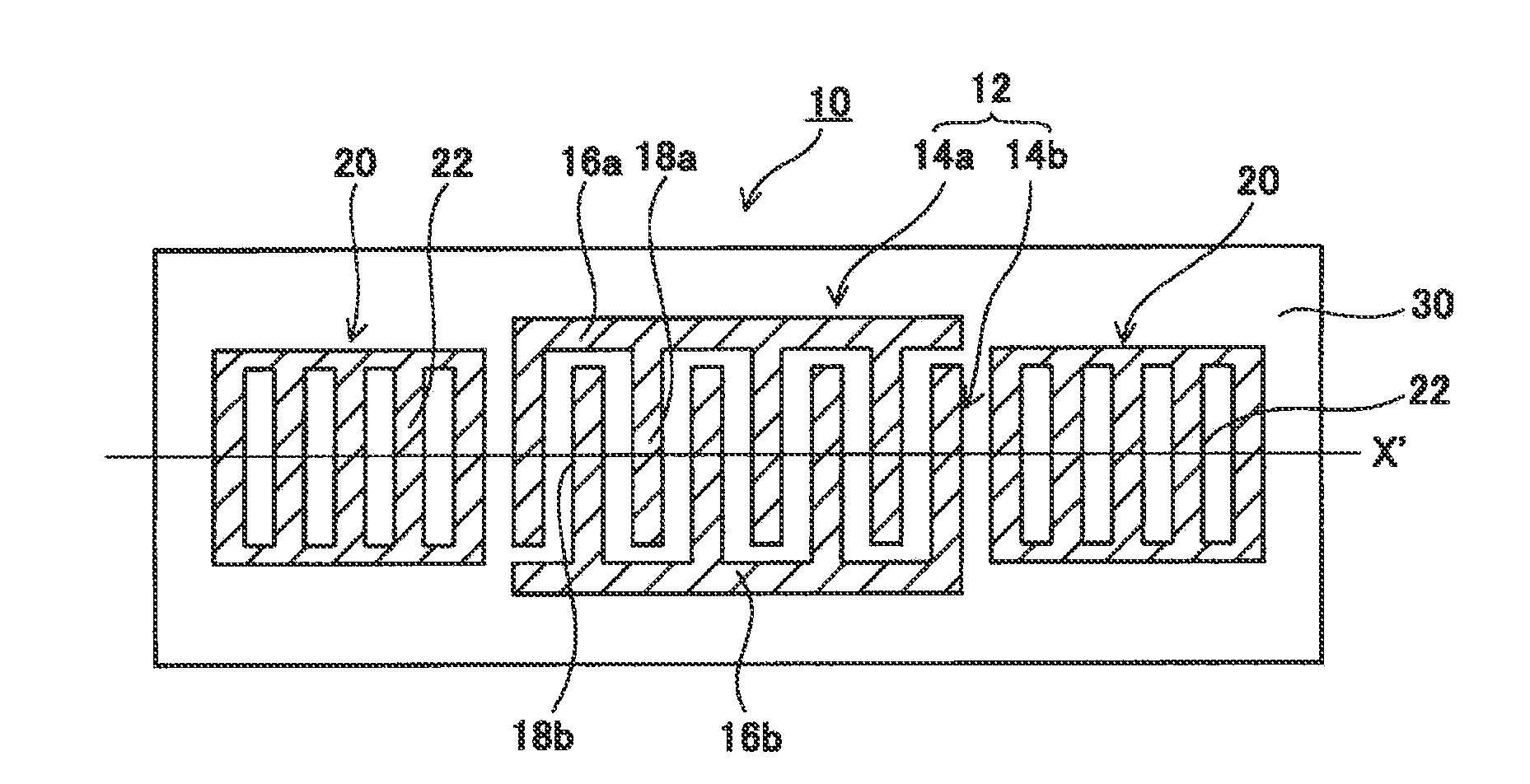
[0019]With the surface acoustic wave resonator according to application example 3, the line occupation rate η satisfies the relationship of

[Expression6]η=-1963.06×(G / λ)3+196.28×(G / λ)2-6.53×(G / λ)-135.99×(H / λ)2+5.817×(H / λ)+0.732-99.99×(G / λ)×(H / λ)(8)

[0020]By fixing η in such a way as to satisfy Equation (8) in the range of the electrode film thickness in Application Example 3, it is possible to keep a secondary temperature coefficient substantially within ±0.01 ppm / ° C.2.


PUM


Abstract

A SAW resonator which, using a quartz crystal substrate with Euler angles (−1.5°≦φ≦1.5°, 117°≦θ≦142°, and 41.9°≦|ψ|≦49.57°), includes an IDT that excites a stop band upper end mode SAW, and an inter-electrode finger groove provided between electrode fingers configuring the IDT. When a wavelength of the SAW is λ, a first depth of the inter-electrode finger groove is G, a line occupation rate of the IDT is η, and an electrode film thickness of the IDT is H, λ, G, η and H satisfy the relationship of 0<H≦0.005λ, 0.01λ≦G≦0.09λ, and 0.18≦η≦0.71.

Description

CROSS-REFERENCE TO RELATED APPLICATIONS[0001]This is a continuation application of U.S. application Ser. No. 12 / 713,461 filed Feb. 26, 2010, which claims priority to Japanese Patent Application No. 2009-050112 filed Mar. 4, 2009 and Japanese Patent Application No. 2009-045359 filed Feb. 27, 2009 all of which are expressly incorporated by reference in their entireties.TECHNICAL FIELD[0002]The present invention relates to a surface acoustic wave resonator, and to a surface acoustic wave oscillator in which the resonator is mounted, and in particular, relates to a type of surface acoustic wave resonator wherein grooves are provided in a substrate surface, and to a surface acoustic wave oscillator in which the resonator is mounted.BACKGROUND ART[0003]In a surface acoustic wave (SAW) device (for example, a SAW resonator), the effect of a SAW stop band, piezoelectric substrate (for example, quartz crystal substrate) cut angle, IDT (interdigital transducer) formation shape, and the like, o...

Claims


Application Information

Patent Timeline
Patent Type & Authority Applications(United States)
IPC IPC(8): H03B5/32H02N1/00
CPCH03H9/02551H03H9/14538H03H9/14594H03H9/25H03H9/0296H03H9/02992H03B5/326
Inventor YAMANAKA, KUNIHITO
Owner SEIKO EPSON CORP
Why Eureka
Try Eureka