
Dental fluoroscopic imaging system

a fluoroscopic imaging and dental technology, applied in the direction of material analysis using wave/particle radiation, instruments, applications, etc., can solve the problems of ignoring dental digital intraoral and extraoral radiography technology, resulting in a 2d or 3d still image, and significant radiation dose to the radiologis

Inactive Publication Date: 2012-08-23
FELDMAN DANIEL UZBELGER
View PDF1 Cites 4 Cited by
  • Summary
  • Abstract
  • Description
  • Claims
  • Application Information

AI Technical Summary

Benefits of technology

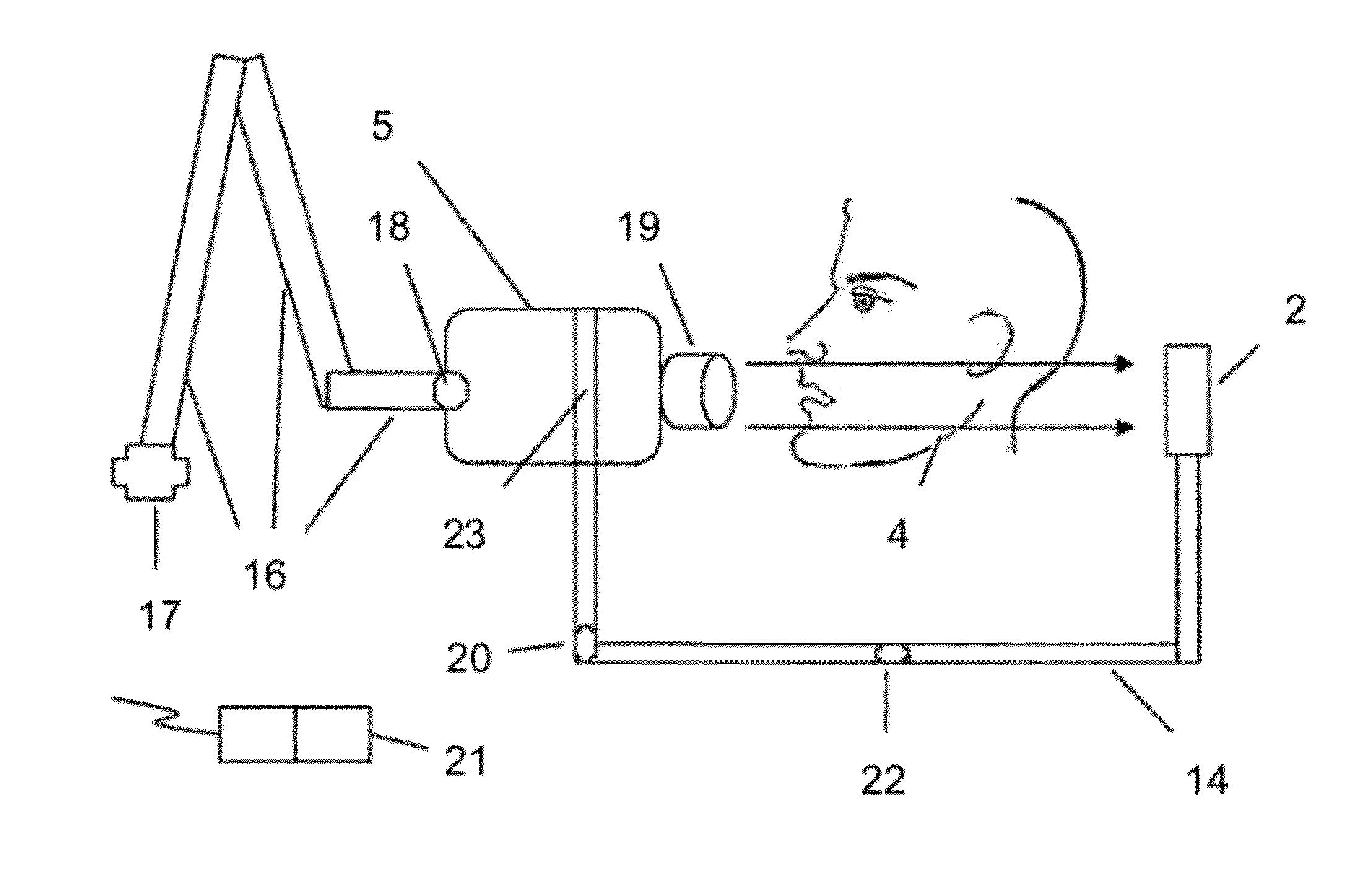
"The present invention is related to dental fluoroscopic imaging and includes a dental fluoroscopic imaging apparatus and a method of producing dental fluoroscopy using a flat panel detector and an emitter. The technical effects of this invention include improved image quality, faster image processing, and reduced patient radiation exposure to low dose gamma rays or x-rays. The dental fluoroscopic imaging apparatus includes a housing containing a converter material, a plate, a collector, a processing unit, and a transmitter capable of reading and transferring digital images. The emitter may operate with direct current, and may utilize a focal spot size within the range from 0.005 to 0.8 mm, a target angle range from 0 to 30 degrees, and a voltage peaks within the range from 35 to 95 kVp. The method of producing dental fluoroscopy may include using a single emitter and a single extraoral flat panel detector positioned in parallel relation facing each other or using two emitters and two extraoral flat panel detectors attached to an O-arm configuration."

Problems solved by technology

A perceived disadvantage of these foregoing dental digital intraoral and extraoral radiography technologies is that the final result is either a 2D or 3D still image.
The placement of the radiologist behind the screen resulted in significant radiation doses to the radiologist.
Despite these efforts, the image receptor configuration using the image intensifier and camera is still too bulky to be used inside the mouth and the image receptor configuration is not sufficiently ergonomic for the dentist so as to be placed extraorally while performing treatments on patients.
Moreover, the proposed configurations in previous inventions only disclose the use of fluoroscopy in a 2D approach using image intensifiers.
In view of the foregoing, it will be apparent that such current technologies are designed to be used in a medical setting and generally are too large to be used in a dental setting.

Method used


Image

  • Dental fluoroscopic imaging system
  • Dental fluoroscopic imaging system
  • Dental fluoroscopic imaging system

Examples


Embodiment Construction

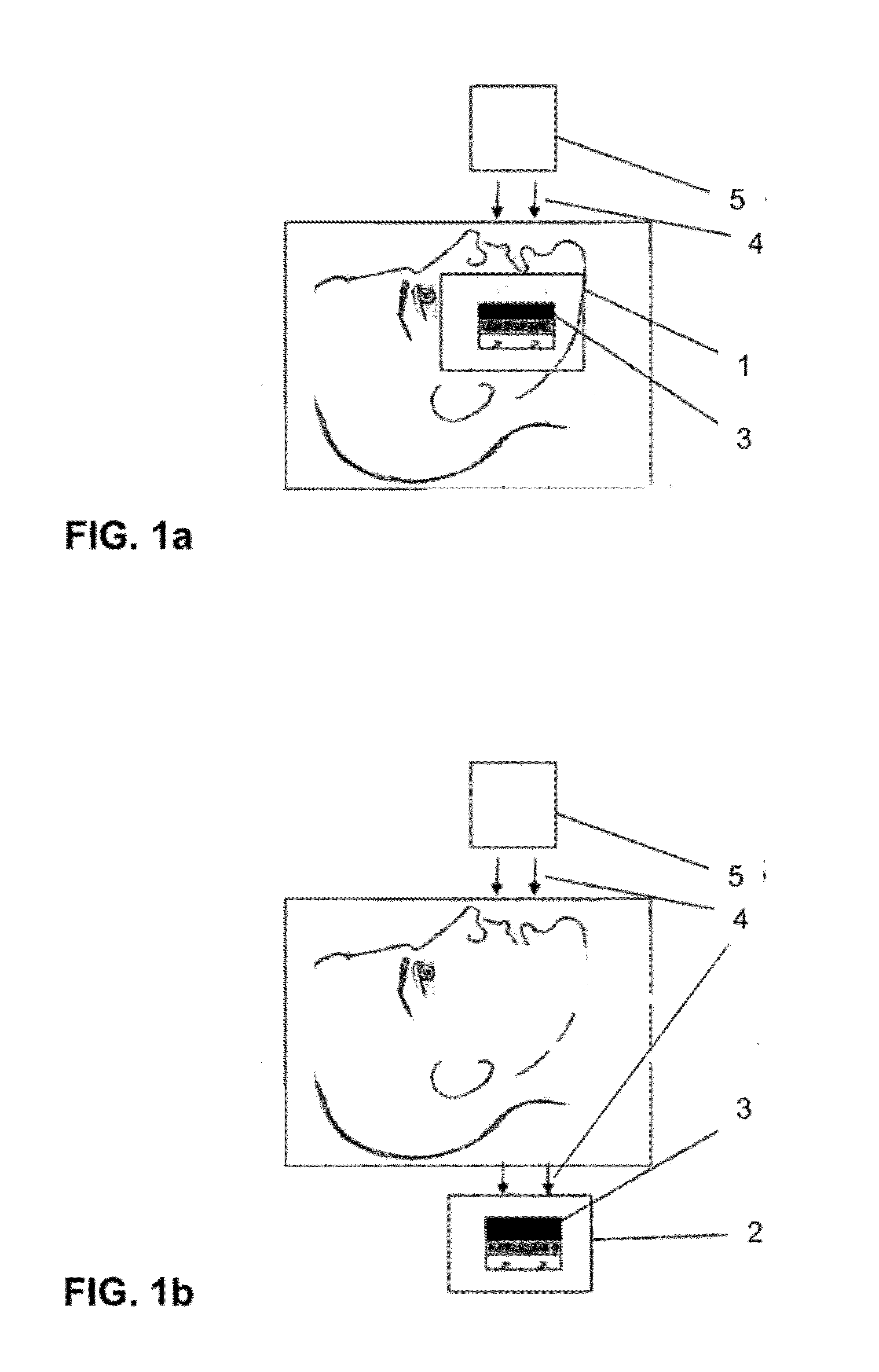
[0045]In accordance with one or more preferred embodiments of the present invention, a dental fluoroscopic imaging apparatus comprises an intraoral flat panel detector 1, and in accordance with one or more preferred embodiments of the present invention, a dental fluoroscopic imaging apparatus comprises an extraoral flat panel detector 2. An intraoral flat panel detector 1 is shown in FIG. 1, and an extraoral flat panel detector 2 is shown in FIG. 2. Whether intraoral or extraoral, each flat panel detector utilizes a converter 3 as illustrated in each of FIGS. 1 and 2. As additionally illustrated in each of FIGS. 1 and 2, systems in accordance with preferred embodiments of the invention include a high frequency direct current (DC) emitter 5 that generates a beam 4 of electromagnetic radiation. The electromagnetic radiation may comprise low dose gamma rays or x-rays.

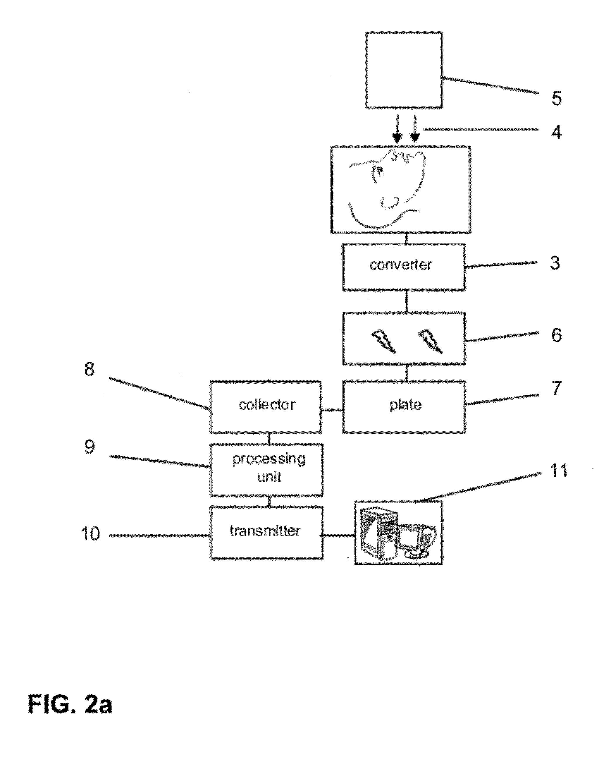
[0046]With reference to FIG. 2a, the flat panel detector is positioned so that the converter 3 receives the beam 4 after...


PUM


Abstract

A dental fluoroscopic imaging system includes a flat panel detector comprising a converter, a plate, a collector, a processing unit, and a transmitter suitable for 2D, intraoral dental fluoroscopy and for 3D extraoral dental fluoroscopy. The converter contains a material capable of transforming low dose radiation received from an emitter after going through the dental examination area into electrical signals. The plate transmits the electric signals to a collector, which amplifies the signals. The processing unit processes the signals into digital images, and the transmitter transfers digital images sequentially to a host computer having software that acquires, processes, transforms, records, freezes, and enhances 2D and 3D images, and compiles videos having video frame rates of between 3 and 100 frames per second. Two dimensional images and video are obtained using a single flat panel detector, while three dimensional images and video are obtained using two flat panel detectors.

Description

CROSS-REFERENCE TO RELATED APPLICATION[0001]The present application is a U.S. continuation application of, and claims priority under 35 U.S.C. to, U.S. nonprovisional patent application Ser. No. 12 / 653,964, filed Dec. 22, 2009, which published as U.S. patent application publication no. 2011 / 0150185, which application and publication are incorporated by reference herein.BACKGROUND OF THE INVENTION[0002]Before the discovery of electromagnetic radiation known as x-rays, techniques and procedures in the field of dentistry were based on purely empirical knowledge. On Nov. 8, 1895, William Conrad Roentgen announced the discovery of this new kind of radiation. Within fourteen days, Otto Walkhoff, a German dentist, took the first dental radiograph of his own mouth. Dr. William James had completed several dental radiographs five months later. In 1913, Coolidge improved the manufacturing techniques of the x-ray tube, which allowed for better control of the quality and quantity of radiographs....

Claims


Application Information

Patent Timeline
Patent Type & Authority Applications(United States)
IPC IPC(8): A61B6/14A61B6/51
CPCA61B6/14A61B6/145A61B6/4014A61B6/588A61B6/4441A61B6/4464A61B6/487A61B6/4411A61B6/512A61B6/51
Inventor FELDMAN, DANIEL UZBELGER
Owner FELDMAN DANIEL UZBELGER
Learn More