Pipette and sealing tip

a technology of sealing tips and pipettes, which is applied in the direction of positive displacement liquid engines, instruments, glassware laboratories, etc., can solve the problems of leakage, other failures, and two potential failure points, and achieve the effect of reducing the need for regular pipette maintenance and calibration, high resistance, and low insertion and ejection forces

a technology of sealing tips and pipettes, which is applied in the direction of positive displacement liquid engines, instruments, glassware laboratories, etc., can solve the problems of leakage, other failures, and two potential failure points, and achieve the effect of reducing the need for regular pipette maintenance and calibration, high resistance, and low insertion and ejection forces

US20120213677A1Active Publication Date: 2012-08-23METTLER TOLEDO RAININ LLC

Image

  • Pipette and sealing tip
  • Pipette and sealing tip
  • Pipette and sealing tip

Examples


Embodiment Construction

[0048]The invention is described below, with reference to detailed illustrative embodiments. It will be apparent that a system according to the invention may be embodied in a wide variety of forms. Consequently, the specific structural and functional details disclosed herein are representative and do not limit the scope of the invention.

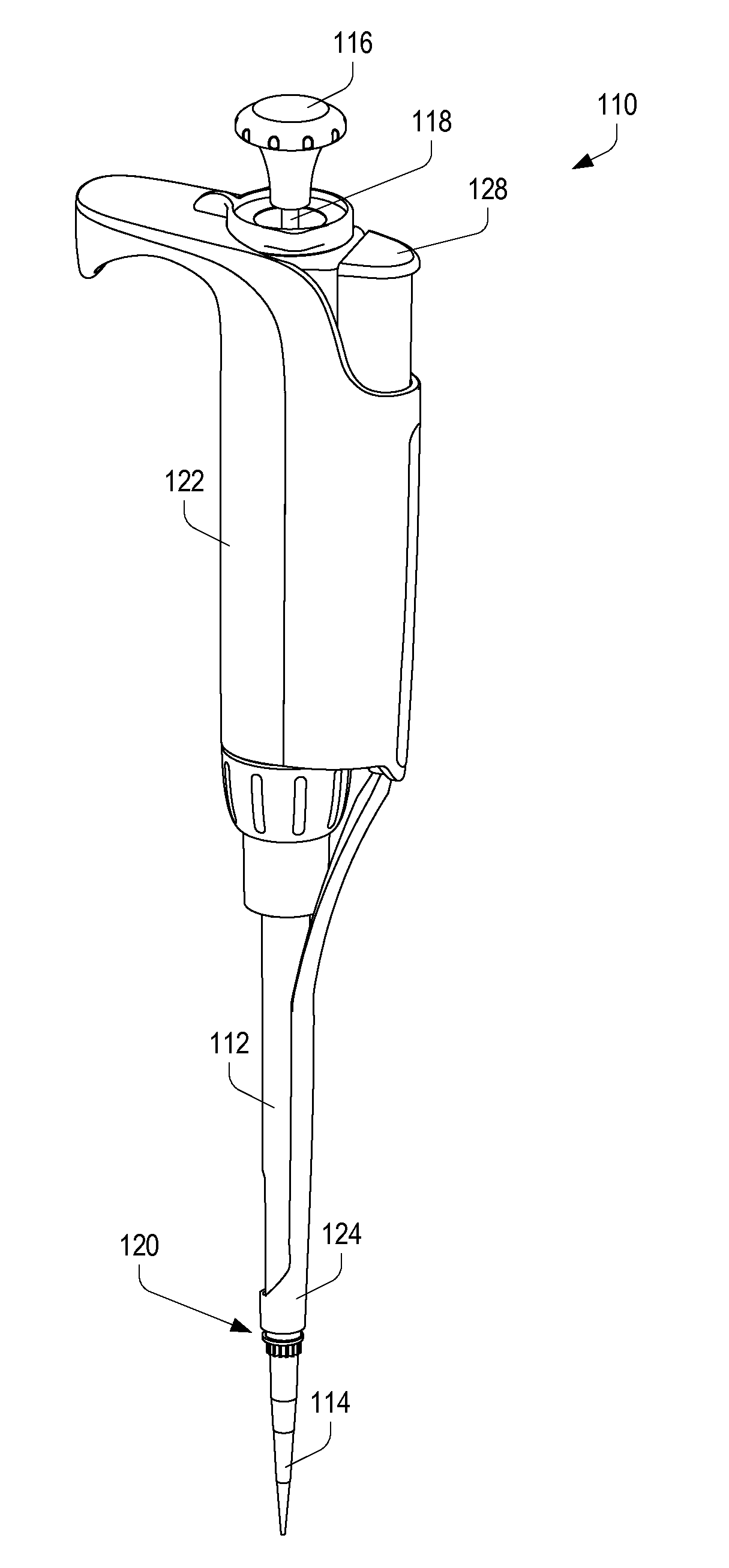
[0049]Referring initially to FIG. 1, a handheld pipette 110 according to the invention is shown. As with traditional pipettes, the illustrated pipette 110 has a tip-mounting shaft 112, and a sealing tip 114 according to the invention is shown mounted on the shaft 112.

[0050]The overall form factor of the pipette 110 and the sealing tip 114 is comparable to that of traditional pipettes, and the combination is used in the same ways and using the same techniques as would be performed using traditional pipettes.

[0051]The pipette has a plunger button 116 connected to a plunger rod 118. The button 116 and rod 118 are spring-biased to a fully-extended positi...


PUM


Abstract

A sealing pipette tip includes features to seal the tip directly against the piston in an air displacement pipette, avoiding the need for a piston seal within the pipette. This configuration reduces potential points of failure, allows the pipette-tip interface to be optimized, and improves liquid handling characteristics of the pipette.

Description

FIELD OF THE INVENTION[0001]The invention relates to air displacement pipettes and sealing disposable tips for such pipettes, and particularly to air displacement pipettes without piston seals, where piston sealing is accomplished via a structure integral to the sealing disposable tip.BACKGROUND OF THE INVENTION[0002]Handheld pipettes are commonly used to dispense or transfer small but accurately measured quantities of liquids.[0003]Air displacement pipettes are the most common variety of handheld pipettes. In an air displacement pipette, a controllable piston is mounted for movement axially within a chamber in the pipette; the piston moves in response to either manual or motorized electronic control. Typically, the piston moves in a chamber in the liquid end, or shaft, of the pipette, to which disposable pipette tips may be mounted.[0004]An air tight seal is formed between the piston and the shaft. With such a seal in place, axial movement of the piston will vary the size of the ai...

Claims


Application Information

Patent Timeline
23 Aug 2012
Publication
US20120213677A1
IPC
B01L3/02
CPC
B01L3/022; B01L3/0275; G01N2035/103; B01L3/021; G01N35/1016; B01L2200/0689; G01N2035/1053; B01L3/02
Inventors
PETREK, JAMES S.