Particle beam therapy system
a technology of beam therapy and beam beam, which is applied in the field of particle beam therapy system, can solve problems such as system complexity
- Summary
- Abstract
- Description
- Claims
- Application Information
AI Technical Summary
Benefits of technology
Problems solved by technology
Method used
Image
Examples
embodiment 1
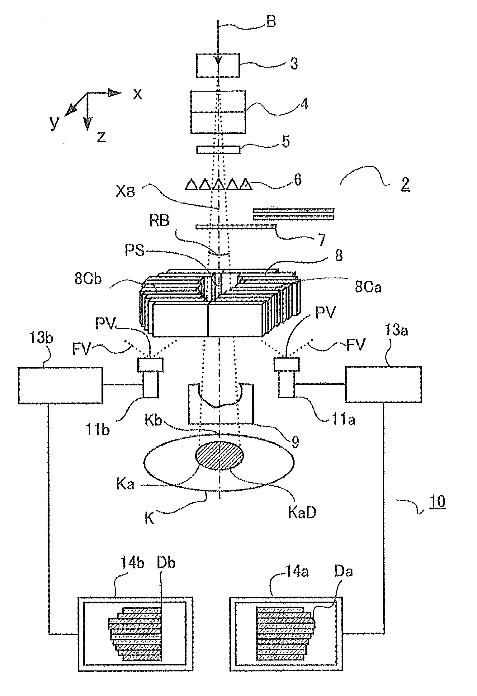
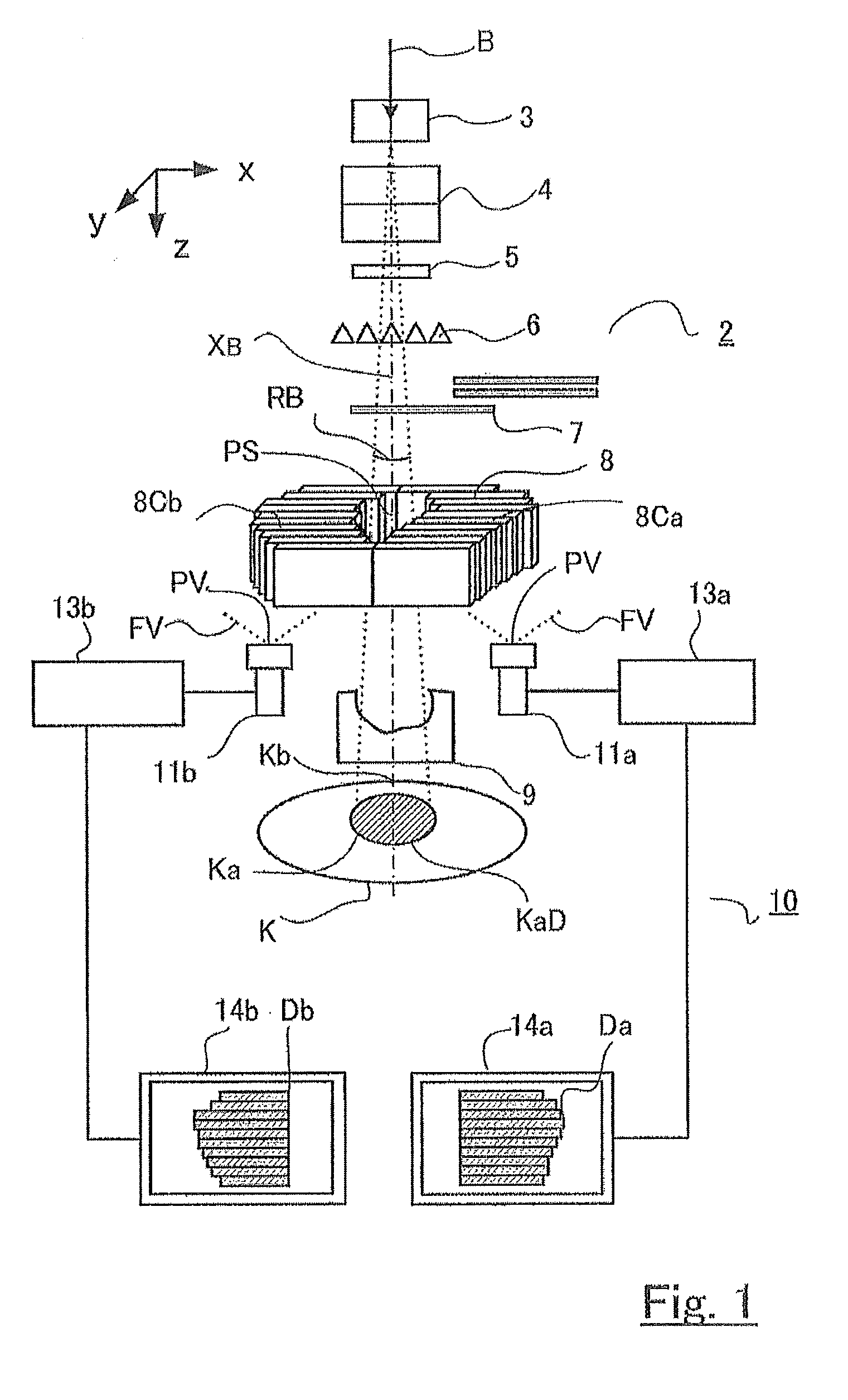
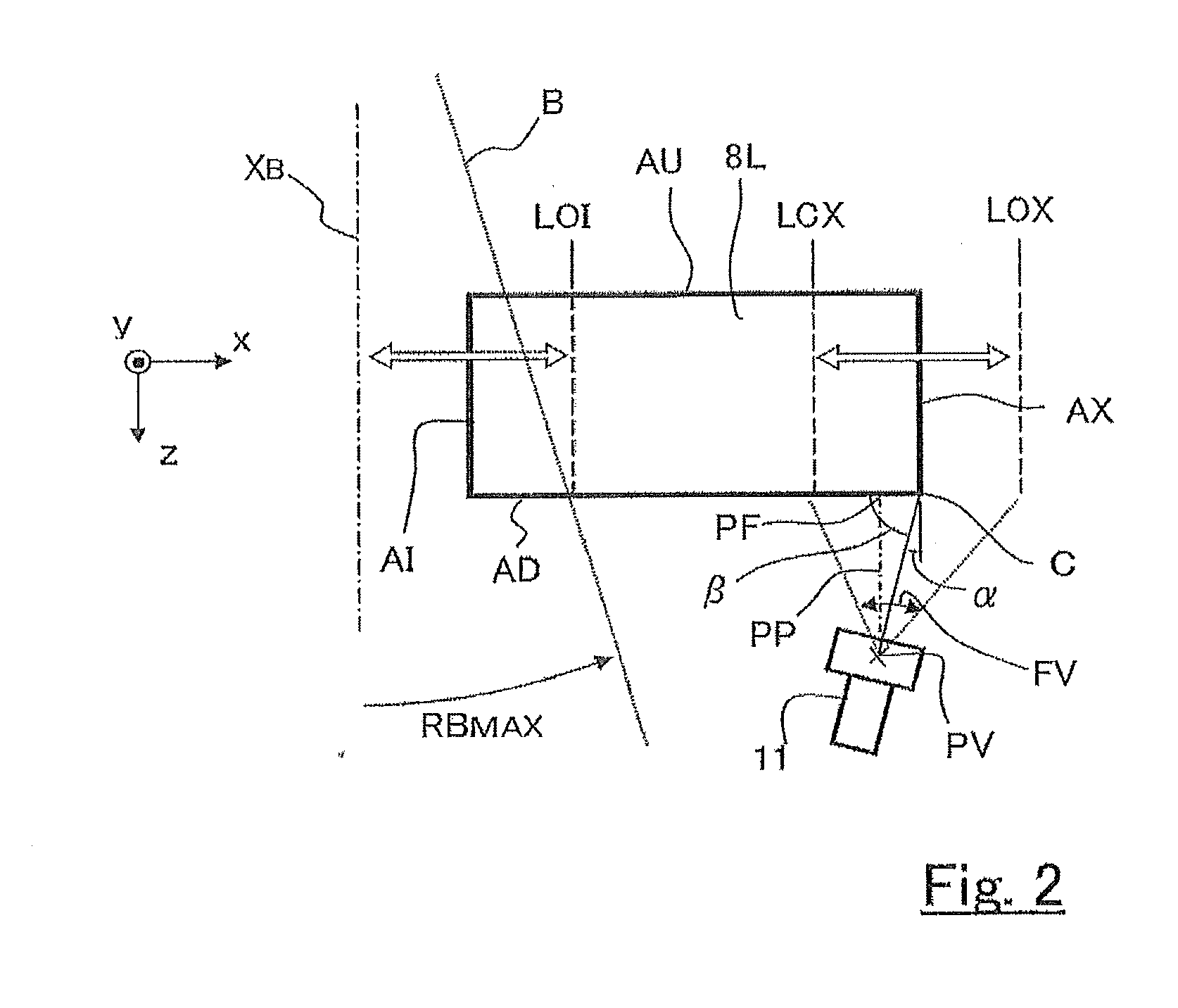
[0019]FIGS. 1 and 2 are diagrams for explaining the configuration of a particle beam therapy system according to Embodiment 1 of the present invention; FIG. 1 is a diagram illustrating the configuration of the whole irradiation system in a particle beam therapy system; FIG. 2 is a diagram illustrating the positional relationship between a multileaf collimator provided in a particle beam therapy system and an image-capturing unit for taking an image of the multileaf collimator. FIG. 3 is a set of diagrams illustrating examples of adjustment of the viewpoint of an image capturing unit (camera) for accurately detecting the position of a leaf, in a particle beam therapy system according to Embodiment 1 of the present invention. FIG. 4 is a set of diagrams for explaining the positional relationship between the leaf plate of a multileaf collimator and the viewpoint of an image-capturing unit in a variant example of particle beam therapy system according to Embodiment 1 of the present inve...
example of embodiment 1
Variant Example of Embodiment 1
[0035]With regard to the relationship between the viewpoint PV and the leaf plate 8L, illustrated in FIG. 3, even in the case where, in addition to Embodiment 1, it is assumed that the orbit is a circumference orbit and the multileaf collimator has a shape such as the outer portion of a sector obtained by simply dividing a ring in the radial direction, there is assumed a basic form in which neighboring side faces {or the tangential lines thereof) cross each other at an angle of 90° and there exists a restriction of α+β=90. Accordingly, in the case where a position where β becomes a right angle is prioritized and, as illustrated in FIG. 3(a), there is performed setting in which the foot PF of the perpendicular line PP drawn from the viewpoint PV is situated in the vicinity of the middle LMX in the driving range of the outer end C, the range where α is positive becomes as narrow as less than the half of the driving range. However, in the case where, as l...
embodiment 2
[0045]In Embodiment 1, there has been described a case where an image is obtained by directly viewing the edge portion C of the downstream side face AD of the leaf plate through the video camera 11; however, in Embodiment 2, there is further provided a mirror; through the mirror, there is taken an image of the edge portion C of the downstream side face AD of the leaf plate 8L.
[0046]FIGS. 5 and 6 are diagrams for explaining the configuration of a particle beam therapy system according to Embodiment 2 of the present invention; FIG. 5 is a diagram illustrating the configuration of the whole irradiation system in a particle beam therapy system; FIG. 6 is a diagram illustrating the positional relationship between a multileaf collimator provided in a particle beam therapy system and a shape monitoring device of the multileaf collimator. FIG. 7 is a set of diagrams for explaining the positional relationship between a leaf plate of a multileaf collimator and a shape monitoring device in a v...
PUM
 Abstract
Description
Claims
Application Information
 - R&D
- Intellectual Property
- Life Sciences
- Materials
- Tech Scout
- Unparalleled Data Quality
- Higher Quality Content
- 60% Fewer Hallucinations
Browse by: Latest US Patents, China's latest patents, Technical Efficacy Thesaurus, Application Domain, Technology Topic, Popular Technical Reports.
© 2025 PatSnap. All rights reserved.Legal|Privacy policy|Modern Slavery Act Transparency Statement|Sitemap|About US| Contact US: help@patsnap.com


