
Medical instruments having video capabiility

a technology of medical instruments and video capacity, which is applied in the field of improved laryngoscopes, can solve the problems of difficult to remove video attachments, require extensive external accessories such as video systems, monitors and wires, and thus are usually quite expensive, and achieve the effects of speeding up regular intubations, facilitating release or detachment, and facilitating easy intubation

Inactive Publication Date: 2012-08-23
BULLARD J ROGER
View PDF3 Cites 8 Cited by
  • Summary
  • Abstract
  • Description
  • Claims
  • Application Information

AI Technical Summary

Benefits of technology

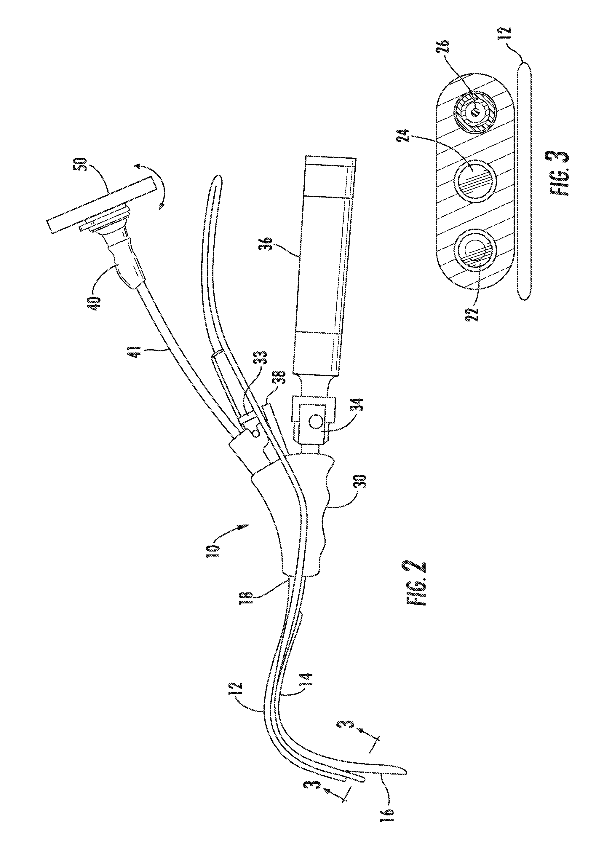
[0016]A quick release adaptor is connected through a hollow tube containing the image bund to the laryngoscope handle at the end opposite the blade. A video imaging device is attached to the adaptor and may be easily released or detached therefrom.
[0017]There are several advantages to using a video laryngoscope. It provides a clearer view of the area which can make difficult intubations easier and speed up regular intubations. One of the advantages of the medical instruments of the present invention is that because the video monitor is easily removable from the body of the instrument, the instrument is easily sterilized. Another advantage is that there are no external accessories needed, such as video systems, monitors, or wires and thus the medical instrument is readily portable and thus the medical instruments of the present invention are less expensive than those with separate imaging devices.

Problems solved by technology

A drawback of laryngoscopes typically found in the prior art is the requirement that the practitioner view through an eyepiece located on the scope itself.
One disadvantage of using medical instruments having a separate imaging screen is that they require extensive external accessories, such as video systems, monitors and wires and thus are usually quite expensive.
Also the image is not convenient to the operator as the operator's head must turn to see the image.
Thus, the video attachment may not be easily removal for sterilization.

Method used


Image

  • Medical instruments having video capabiility
  • Medical instruments having video capabiility
  • Medical instruments having video capabiility

Examples


Embodiment Construction

)

[0028]The present invention now will be described more fully hereinafter with reference to the accompanying drawings, in which preferred embodiments of the invention are shown. This invention may, however, be embodied in many different forms and should not be construed as limited to the embodiments set forth herein; rather these embodiments are provided so that this disclosure will be through and complete and will fully convey the scope of the invention to those skilled in the art. Like numbers refer to the elements throughout.

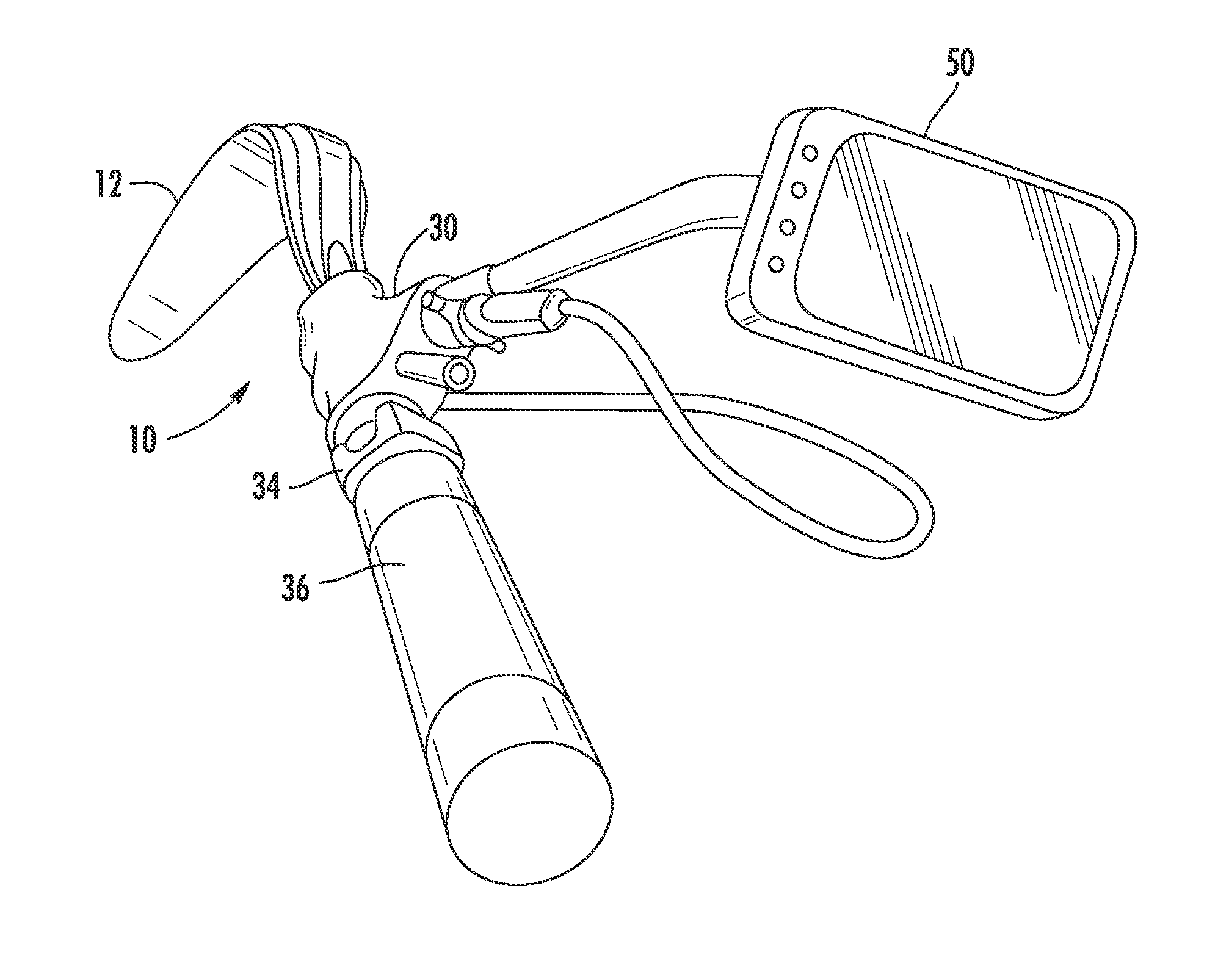
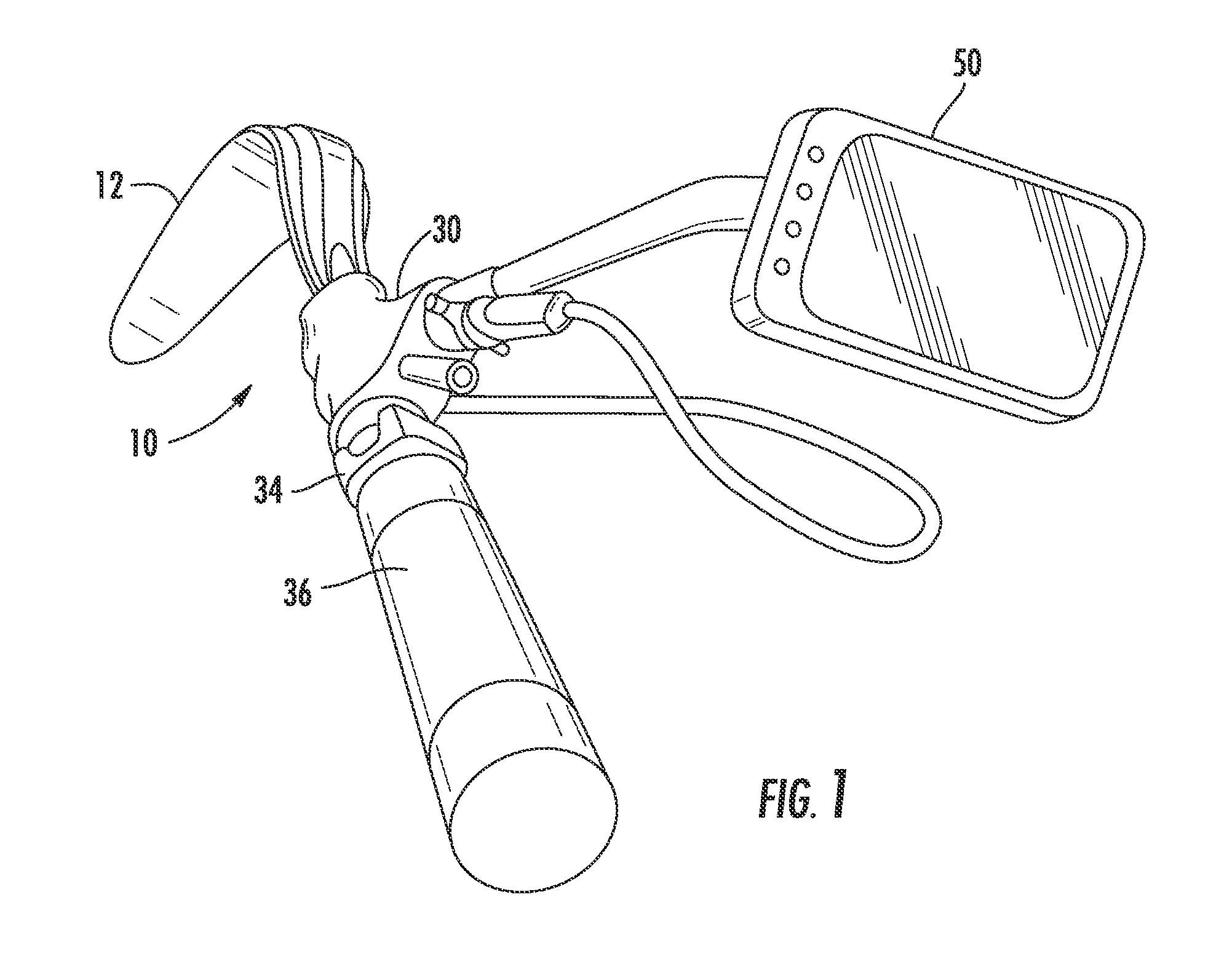
[0029]Generally speaking, FIG. 1 shows an overview of the laryngoscope 10 of the present invention illustrating a laryngoscope scope, having a rigid elongated blade 12, a handle 30, a power source 34 and an image viewer 50. It should be understood that although the invention if described in relation to a laryngoscope that it is equally adaptable to other medical instruments such as bronchoscopes, nasopharyngoscopes, cystocopes, gastroscopes and arthroscopes.

[...


PUM


Abstract

An improved medical instrument having a rigid blade, a handle, a power source, and an easily removable video imaging device such as a video monitor is provided. The distal end comprises a series of channels extending along the blade in which one houses a fiber optic illuminating bundle for transmitting light into an area beyond said distal end of the blade, another channel carries an image bundle for transmitting visual images from said area to a position adjacent said proximal end of said blade and a third channel houses an intubation tube installation device or other instrument. The images are carried through the channel and the handle to the video imaging device. A quick release adaptor is connected through a hollow tube containing the image bundle to the laryngoscope handle at the end opposite the blade. The video imaging device is attached to the adaptor and may be easily release or detached therefrom.

Description

BACKGROUND OF THE INVENTION[0001]1. Field of the Invention[0002]The present invention relates to improved medical instruments for visualizing interior portion of the human anatomy. More particularly, the present invention relates to an improved laryngoscope having an adapter for connecting a laryngoscope to a readily detachable video imaging device, such as a video monitor.[0003]2. Description of Related Art[0004]The field of laryngoscopy includes medical diagnostic and therapeutic disciplines which utilize laryngoscopes to view the laryngeal area of the throat with minimal intrusion. Laryngoscopes are anatomically shaped rigid fiber optic instruments designed to aid intubation, i.e., to facilitate endotracheal intubation of a patient during surgery to provide a positive air passageway for the administration of anesthesia and / or for the mechanical ventilation of the lungs of a patient.[0005]By way of background, the epiglottis normally over lies the glottis opening into the larynx t...

Claims


Application Information

Patent Timeline
Patent Type & Authority Applications(United States)
IPC IPC(8): A61B1/267
CPCA61B1/00052A61B1/267A61B1/00121
Inventor BULLARD, J. ROGER
Owner BULLARD J ROGER
Learn More