Method and apparatus for bypass graft

a bypass graft and apparatus technology, applied in the field of bypass grafts, can solve the problems of difficult implementation of existing grafts, frequent hospitalization and death, and loss of heart capacity, and achieve the effect of improving fluid flow mixing

Inactive Publication Date: 2012-08-23
RICHARDSON CHARLES L +2
View PDF6 Cites 4 Cited by
  • Summary
  • Abstract
  • Description
  • Claims
  • Application Information

AI Technical Summary

Benefits of technology

[0006]These and other shortcomings of the prior art are addressed by the present invention, which according to one aspect provides a vascular connector, having: a main tube having a channel for fluid flow therethrough and opposed ends adapted to be connected to a vascular structure; and at least one inlet tube having a channel for fluid flow therethrough, a proximal end intersecting the main tube, and a distal end adapted to be connected to a vascular structure, wherein the geometry of the intersection between the at least one inlet tube and the main tube is configured to enhance mixing of fluid flowing from the inlet tube with fluid flowing in the main tube.

Problems solved by technology

Coronary artery disease is a major medical problem, resulting in frequent hospitalization and death.
The resulting loss of blood flow causes a loss in heart capacity.
If an artery becomes completely blocked a heart attack will result.
Existing grafts are difficult to implement, requiring careful measurement, and traumatic harvesting of vessels from the patient.
Furthermore, known techniques of connecting blood vessels to each other do not result in hydrodynamically ideal flow configurations of the connected vessels.
This can cause turbulence and restricted flow in the bypass graft.

Method used


Image

  • Method and apparatus for bypass graft
  • Method and apparatus for bypass graft
  • Method and apparatus for bypass graft

Examples


Embodiment Construction

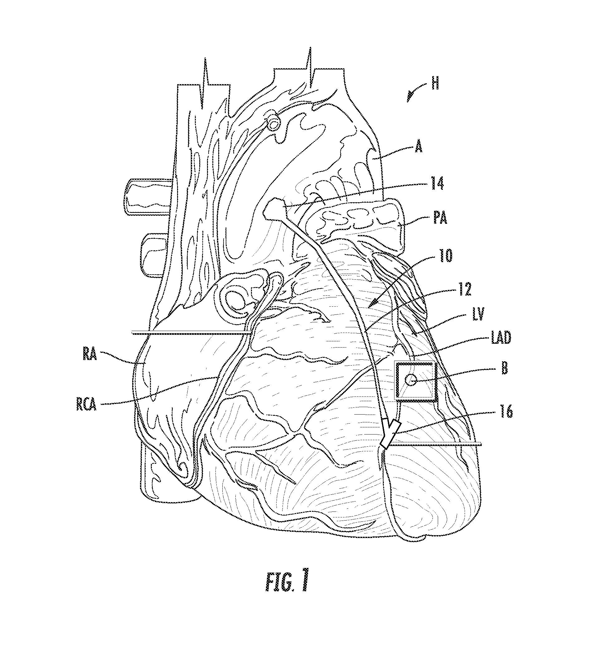
[0038]Referring to the drawings wherein identical reference numerals denote the same elements throughout the various views, FIG. 1 shows a heart “H” including the left ventricle “LV”, right atrium “RA”, left pulmonary artery “PA” and aorta “A”. The left anterior descending artery “LAD” and right coronary artery “RCA” extend down the front surface of the heart H. Each of these arterial structures has multiple branches which supply oxygenated blood to the heart muscle tissue. Frequently the LAD or RCA will become partially or totally occluded, preventing normal operation, for example by a blockage at point “B”. A coronary artery bypass graft (CABG) 10 according to the present invention is implemented on the illustrated heart H. the CABG includes a graft vessel 12 which extends between an aortic connection 14 and a connector 16. The connector 16 provides a fluid connection between the graft 14 and a vessel (i.e. a portion of the LAD or RCA) downstream of the blockage B. While the prese...


PUM

PropertyMeasurementUnit
angleaaaaaaaaaa
angleaaaaaaaaaa
cross-sectional areaaaaaaaaaaa

Abstract

A vascular connector includes a main tube having a channel for fluid flow therethrough and opposed ends adapted to be connected to a vascular structure; and at least one inlet tube having a channel for fluid flow therethrough, a proximal end intersecting the main tube, and a distal end adapted to be connected to a vascular structure.

Description

CROSS-REFERENCE TO RELATED APPLICATIONS[0001]This application is a Continuation of application Ser. No. 11 / 857,317, which is currently pending.BACKGROUND OF THE INVENTION[0002]This invention relates generally to bypass grafts and more particularly to devices and methods for coronary bypass grafts.[0003]Coronary artery disease is a major medical problem, resulting in frequent hospitalization and death. It occurs when there is a narrowing in one of the heart's arterial systems that supplies oxygenated blood to the heart muscle. The resulting loss of blood flow causes a loss in heart capacity. If an artery becomes completely blocked a heart attack will result.[0004]It is known to surgically treat coronary artery disease using coronary artery bypass grafts (“CABG”). In this procedure, vessels harvested from another part of the patient's body are used to construct a bypass route from the aorta to a point downstream of the narrowing or blockage.[0005]Existing grafts are difficult to imple...

Claims


Application Information

Patent Timeline
Patent Type & Authority Applications(United States)
IPC IPC(8): A61F2/06B23K9/02
CPCA61F2/064A61B17/11A61B2017/1135A61B2017/1132A61B2017/1107
Inventor RICHARDSON, CHARLES L.KELLAR, FRANZ W.FAULKNER, DONALD G.
Owner RICHARDSON CHARLES L
Why Eureka
Try Eureka