
Calibration system for simultaneous calibration of multiple motion capture elements

a motion capture and calibration system technology, applied in the field of simultaneous calibration of multiple motion capture elements, can solve the problems of reduced price of available solutions, limited general accuracy of known motion capture sensors or elements, and reduced cost of motion capture elements, so as to increase the accuracy of motion capture elements and reduce the cost

Active Publication Date: 2012-08-23
NEWLIGHT CAPITAL LLC
View PDF0 Cites 26 Cited by
  • Summary
  • Abstract
  • Description
  • Claims
  • Application Information

AI Technical Summary

Benefits of technology

[0009]Embodiments of the invention enable a calibration system for simultaneous calibration of multiple motion capture elements. More than one or large numbers of motion capture sensors may be calibrated simultaneously which reduces the cost and increases the accuracy of motion capture elements. The calibrated motion capture elements may be utilized in a myriad of applications to provide more accurate motion capture data, including but not limited to healthcare compliance, sporting, gaming, military, fire, police, virtual reality, industrial, retail loss tracking, security, baby and elderly monitoring and other applications. The motion capture data may be obtained from one or more users and / or instrumented pieces of sporting equipment. Embodiments of the invention may communicate with the motion capture elements during calibration via hardwired or wireless communications depending on the communications capabilities of the specific motion capture elements. The formats of motion capture elements that may be calibrated in one or more embodiments of the invention include all types of integrated circuits, memory cards with integrated gyroscopes and / or accelerometers, including but not limited to secure digital (SD) cards, subscriber identity module (SIM) cards, printed circuit boards (PCBs) or any type of mobile device or any other device having an accelerometer and / or gyroscope for example. One or more embodiments of the mobile devices that may include accelerometers and for example a small mountable computer include IPHONE® and other cell phones, an IPOD® SHUFFLE® or IPOD® NANO® that may or may not have integrated displays, and which are small enough to couple with a human or mount on a shaft of a piece of sporting equipment.

Problems solved by technology

The use of motion capture elements for various activities is increasing as the size of the devices decreases and the price of available solutions decreases.
Although the use of accelerometers and gyroscopes is increasing, the general accuracy of known motion capture sensors or elements is limited for a variety of reasons.
One reason for the limited accuracy of accelerometers and gyroscopes is that there is a cost associated with calibrating each device.
Another limitation of known motion capture sensors occurs as a result of the mounting process when the motion capture discrete components are coupled with a mounting element.
For example, when coupling a chip-based sensor to a printed circuit board, the temperature changes inherent in the manufacturing process may rise considerably, which changes the characteristics of the sensor, requiring further calibration.
To summarize, motion capture data is generally not calibrated in known devices to provide high accuracy due to manufacturing techniques and extra costs involved with calibration.
Some devices, such as mobile phones may include motion capture elements on relatively large PCB's that are generally not calibrated for highly accurate motion capture.
This is due to the size of the PCB's that are relatively large and can only be calibrated one at a time with known calibration machines.

Method used


Image

  • Calibration system for simultaneous calibration of multiple motion capture elements
  • Calibration system for simultaneous calibration of multiple motion capture elements
  • Calibration system for simultaneous calibration of multiple motion capture elements

Examples


Embodiment Construction

[0017]A calibration system for simultaneous calibration of multiple motion capture elements will now be described. In the following exemplary description numerous specific details are set forth in order to provide a more thorough understanding of the ideas described throughout this specification. It will be apparent, however, to an artisan of ordinary skill that embodiments of ideas described herein may be practiced without incorporating all aspects of the specific details described herein. In other instances, specific aspects well known to those of ordinary skill in the art have not been described in detail so as not to obscure the disclosure. Readers should note that although examples of the innovative concepts are set forth throughout this disclosure, the claims, and the full scope of any equivalents, are what define the invention.

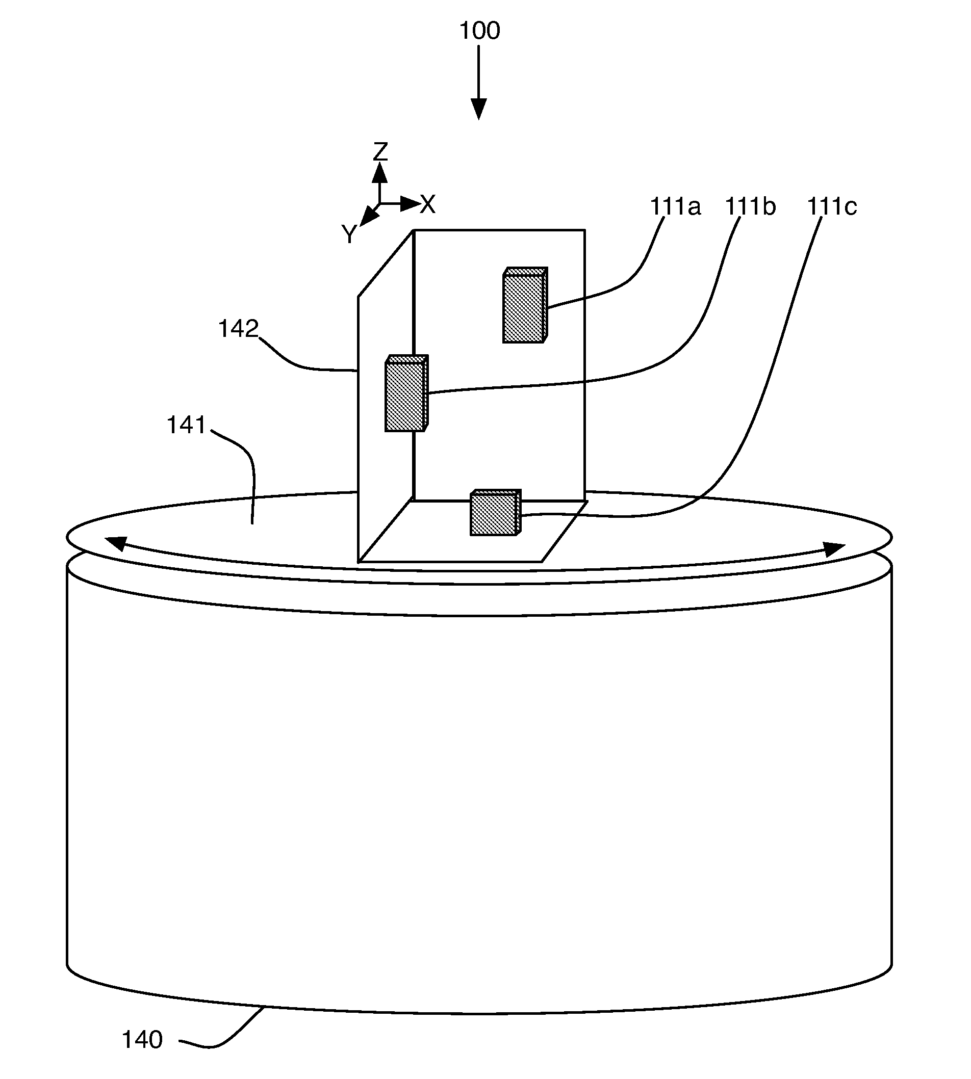
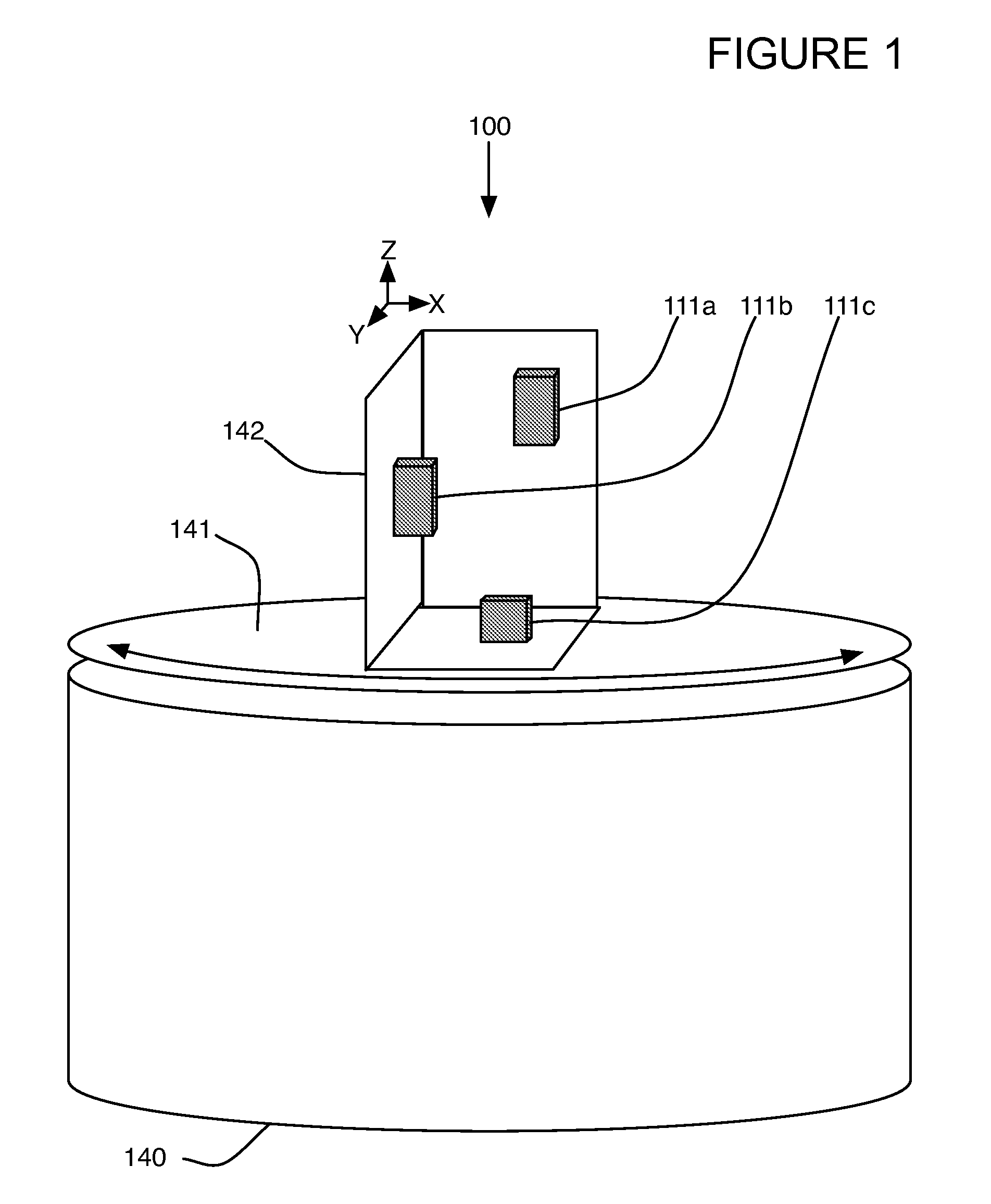
[0018]FIG. 1 illustrates an embodiment of the calibration system for simultaneous calibration of multiple motion capture elements. In one or more embod...


PUM


Abstract

A calibration system for simultaneous calibration of multiple motion capture elements (MCEs) of at least one type (accelerometer and / or gyroscope). Includes motion and / or rotational element coupled to a base and configured to move and / or rotate multiple MCEs mounted on a mount in and / or about at least one axis. For one axis movement embodiments, after each motion and / or axial rotation, the motion and / or rotational mount itself is rotated for example manually, so the mount points in a different direction, i.e., the Z axis. In a single axis embodiment, this is performed twice so that each axis of the MCEs experience motion and / or rotation about three axes. The motion capture data is sampled and used in calculation of a 3×3 calibration matrix. The physical format of the motion capture sensors may be any format including chip, memory or SIM card format, PCB format, mobile computers / phones.

Description

[0001]This application is a continuation-in-part of U.S. Utility patent application Ser. No. 13 / 358,522 filed Jan. 25, 2012, which is a continuation-in-part of U.S. Utility patent application Ser. No. 13 / 306,869 filed Nov. 29, 2011, and is also a continuation-in-part of U.S. Utility patent application Ser. No. 13 / 351,429 filed Jan. 17, 2012, which is a continuation-in-part of U.S. Utility patent application Ser. No. 13 / 298,158 filed Nov. 16, 2011, which is a continuation-in-part of U.S. Utility patent application Ser. No. 13 / 267,784 filed Oct. 6, 2011, which is a continuation-in-part of U.S. Utility patent application Ser. No. 13 / 219,525 filed Aug. 26, 2011, which is a continuation-in-part of U.S. Utility patent application Ser. No. 13 / 191,309 filed Jul. 26, 2011, which is a continuation-in-part of U.S. Utility patent application Ser. No. 13 / 048,850 filed Mar. 15, 2011, which is a continuation-in-part of U.S. Utility patent application Ser. No. 12 / 901,806 filed Oct. 11, 2010, which ...

Claims


Application Information

Patent Timeline
Patent Type & Authority Applications(United States)
IPC IPC(8): G06F19/00G01P21/00G01C25/00G01P21/02
CPCA63B49/00A63B53/00A63B2220/12G01C25/005A63B2225/54A63B2220/00A63B2225/02A63B2225/50
Inventor BENTLEY, MICHAELBOSE, BHASKAR
Owner NEWLIGHT CAPITAL LLC
Learn More