Manufacturing facility with robotic carrier and method of manufacturing

a manufacturing facility and robotic carrier technology, applied in the direction of metal working equipment, assembly machines, metal-working equipment, etc., can solve the problems of increasing the maintenance cost associated with the reconfiguration of the manufacturing facility, the type of manufacturing facility has not proved very flexible, and the configuration has not provided the necessary manufacturing flexibility. , to achieve the effect of preventing manufacturing flexibility, costing significant amounts of money to install and maintain

Inactive Publication Date: 2012-08-30
DURR ECOCLEAN INC
View PDF1 Cites 35 Cited by
  • Summary
  • Abstract
  • Description
  • Claims
  • Application Information

AI Technical Summary

Benefits of technology

[0007]The novel manufacturing facility of the present invention eliminates that part of a manufacturing facility known to create bottlenecks in the manufacturing process, cost significant amounts of money to install and maintain, and prevent the manufacturing flexibility required of modern manufacturing facilities. The carrier of the present invention provides advancements over prior art automatic guided vehicles that have had limited capacity and have only been able to deliver raw material to predetermined destinations. The carrier of the present invention provides a capability of moving between any of a number of work stations or assembly station arranged in a manufacturing facility to facilitate the manufacturing of a workpiece as desired. Furthermore, the carrier of the present invention includes a robotic manipulator that is adapted to both introduce the workpiece to a work station or assembly station in a dimensionally accurate location, ...

Problems solved by technology

However, the robotic manipulator typically performed a single task at a particular work station and was immovable.
This type of manufacturing facility has not proved very flexible because the robotic manipulator has typically been only able to perform a single task at a given work station.
However, these configurations have not proven to provide necessary manufacturing...

Method used


Image

  • Manufacturing facility with robotic carrier and method of manufacturing
  • Manufacturing facility with robotic carrier and method of manufacturing
  • Manufacturing facility with robotic carrier and method of manufacturing

Examples


Embodiment Construction

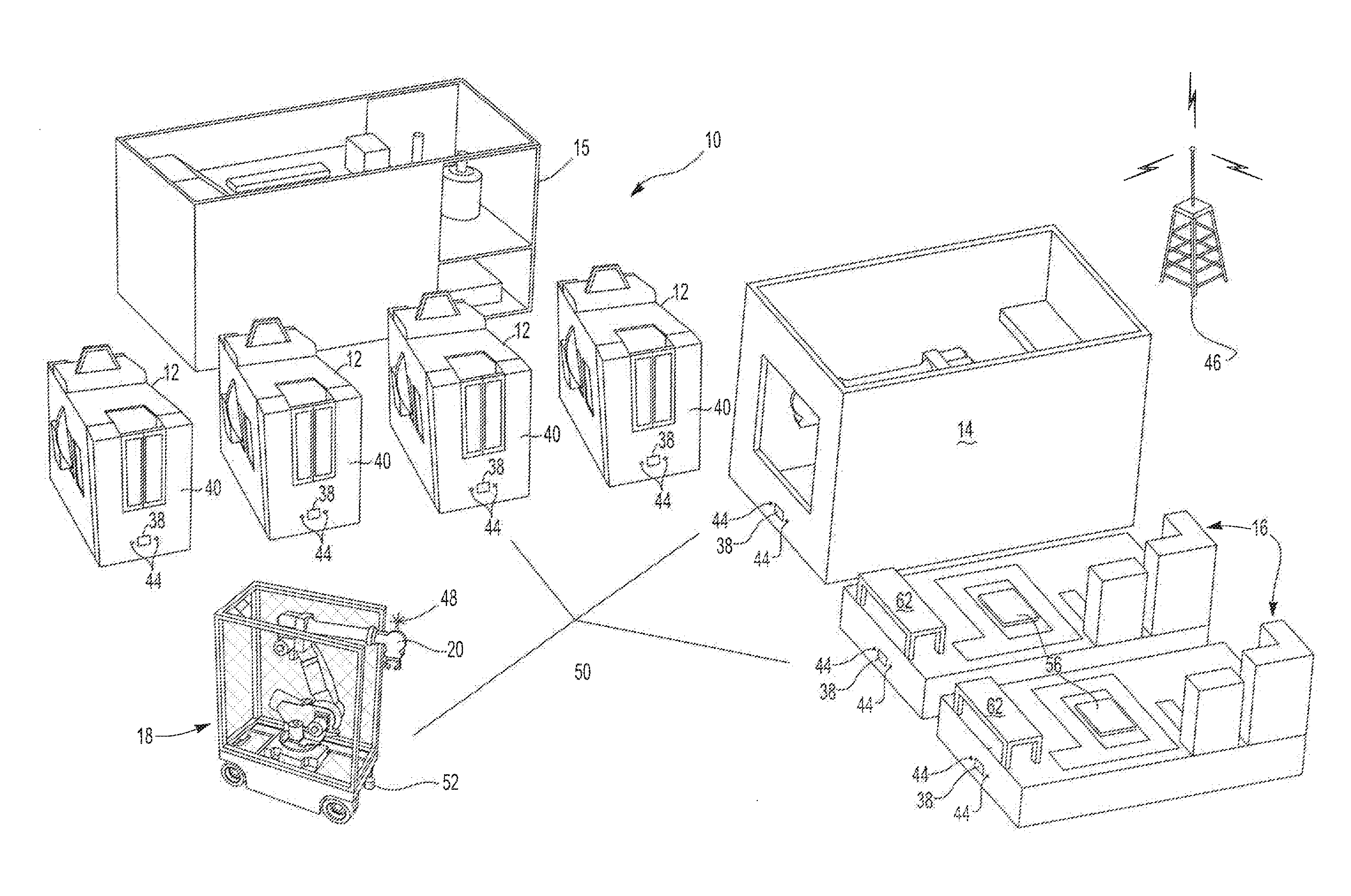
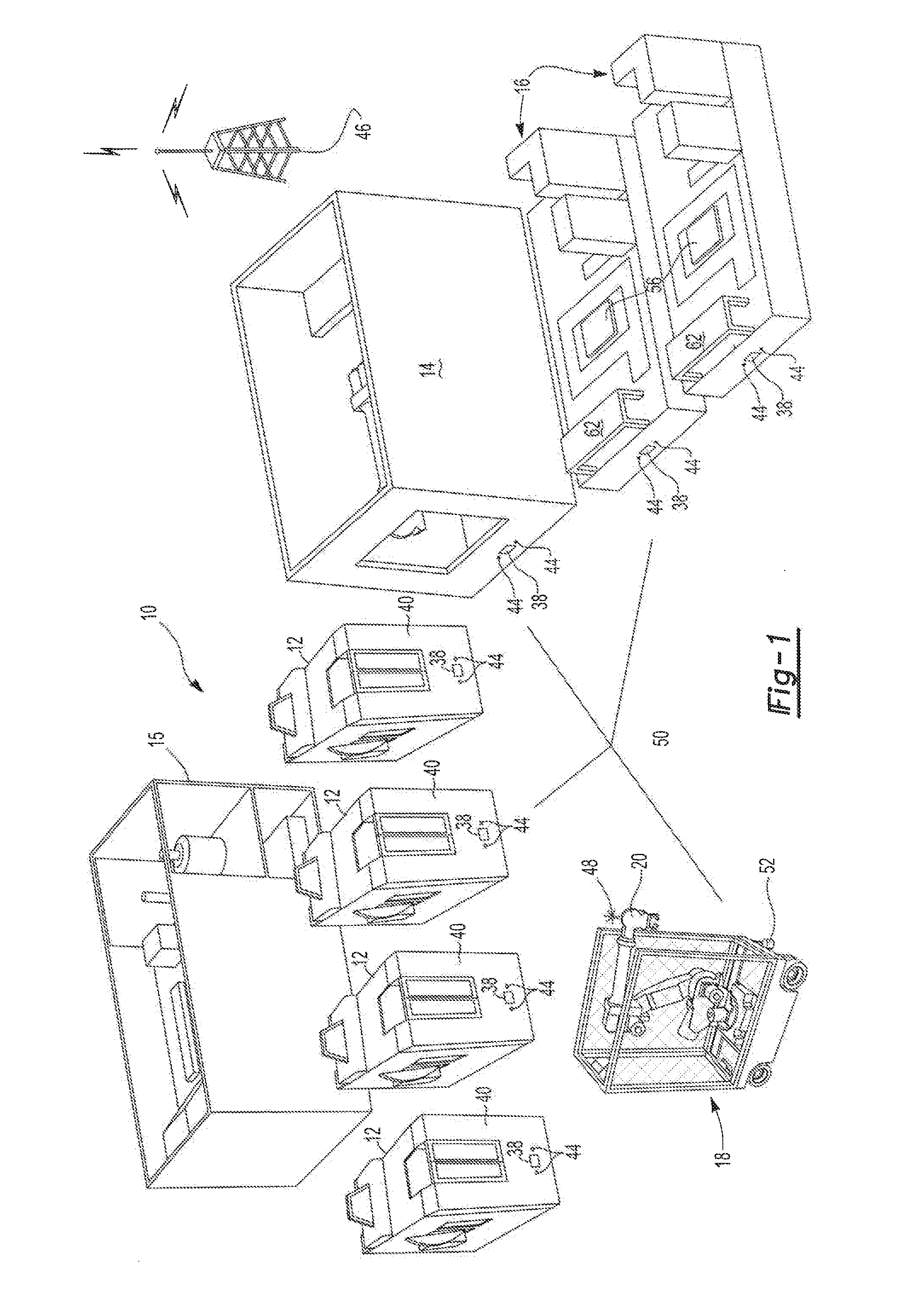
[0016]Referring to FIG. 1, the workpiece manufacturing facility of the present invention is generally shown at 10. The facility 10 includes a work station 12, or as contemplated by the inventor, a plurality of work stations 12 for performing work on a workpiece W. For example, the work station 12 includes tooling (not shown) used to machine and provide a dimensionally accurate configuration to the workpiece in a known manner. The workpiece is contemplated to be any product including, head cylinders, engine blocks, oil pump housings, or equivalent components manufactured by way of casting or other metal forming.

[0017]It is contemplated that a given workpiece can be completely machined to a dimensionally accurate configuration in a single work station, or be machined in a plurality of work stations as shown in FIG. 1. Therefore, a workpiece W is either made dimensionally accurate in a single work station 12, or is moved between a plurality of work stations 12, each of which advance th...


PUM

PropertyMeasurementUnit
Energyaaaaaaaaaa
Configurationaaaaaaaaaa

Abstract

A workpiece manufacturing facility includes a plurality of workstations capable of performing work on a workpiece to dimensionally advance a configuration of the workpiece. A plurality of assembly stations is capable of assembling components of the workpiece to the workpiece. A carrier is moveable between any of the work stations and between any of the assembly stations. The carrier transports at least one workpiece between at least one work station and at least one assembly station. The carrier includes a robotic manipulator capable of introducing the workpiece to the workstations and the assembly stations in a dimensionally accurate position and the robotic manipulator is capable of performing work on the workpiece.

Description

BACKGROUND OF THE INVENTION[0001]The present invention relates generally toward a new facility and method of manufacturing a workpiece. More specifically, the present invention relates to a manufacturing facility and method of manufacturing a workpiece making use of a carrier that includes a robotic manipulator and is movable between various work and assembly stations.[0002]Since the advent of mass production, moving assembly lines have been used to transfer a workpiece through a manufacturing facility stopping or delivering the workpiece at different work or assembly stations. In some instances, the moving assembly line stops for a short period of time allowing work to be performed on the workpiece, after which a workpiece is moved to the next work or assembly station.[0003]The introduction of robotic manipulators to mass production facilities increased the pace by which a moving assembly line could transfer a workpiece between work stations. However, the robotic manipulator typica...

Claims


Application Information

Patent Timeline
IPC IPC(8): B23P11/00B23P19/00
CPCB23P21/004Y10T29/49826Y10T29/534
Inventor IMMEKUS, WILLIAM J.
Owner DURR ECOCLEAN INC
Why Eureka
Try Eureka