Repair alignment method and apparatus for turbine components

a technology for turbine components and alignment methods, which is applied in the direction of soldering apparatus, turbines, auxillary welding devices, etc., can solve the problems of bending, cracking, corrosion, physical damage, etc., and achieves the effect of improving the stability of the engine, avoiding bending, and avoiding bending

Inactive Publication Date: 2012-08-30
GENERAL ELECTRIC CO
View PDF17 Cites 16 Cited by
  • Summary
  • Abstract
  • Description
  • Claims
  • Application Information

AI Technical Summary

Problems solved by technology

During operation, turbine components, in particular the airfoils in the compressor, are exposed to a high velocity air stream that can lead to oxidation, corrosion, physical damage, and cracking from thermal cycling.
Because turbine components are complex in design, are made of relatively expensive materials, and are expensive to manufacture, it is ge

Method used


Image

  • Repair alignment method and apparatus for turbine components
  • Repair alignment method and apparatus for turbine components
  • Repair alignment method and apparatus for turbine components

Examples


Embodiment Construction

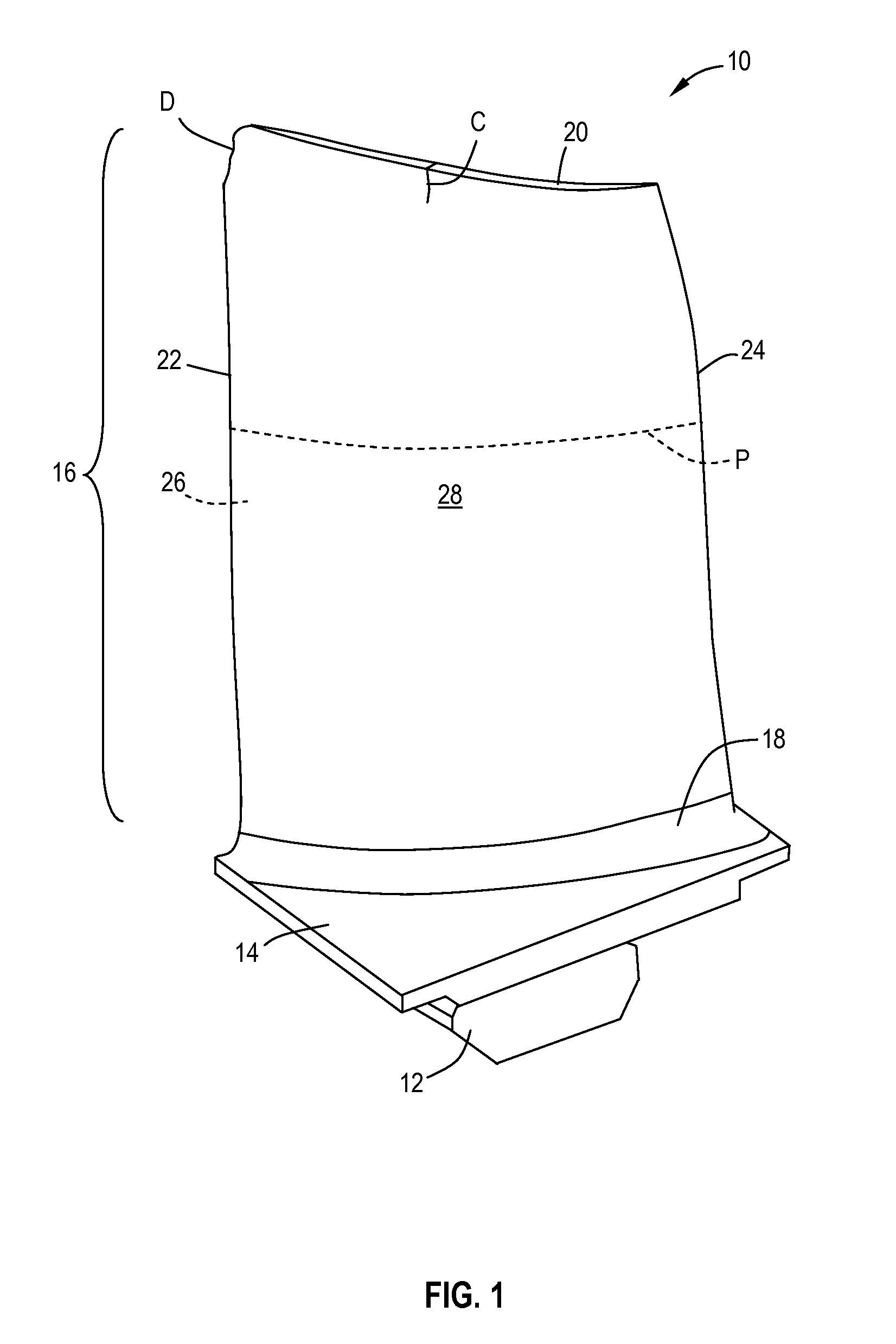
[0025]Referring to the drawings wherein identical reference numerals denote the same elements throughout the various views, FIG. 1 shows a compressor blade 10 of a gas turbine engine. It will be understood that the principles of the present invention are also applicable to other kinds of airfoils. The blade 10 includes a dovetail 12 used to mount the blade 10 to a compressor disk wheel (not shown), an arcuate platform 14, and an airfoil 16 having a root 18, a tip 20, a leading edge 22, a trailing edge 24, a concave pressure side 26 and a convex suction side 28.

[0026]Typically, such blades are made of an alloy based on at least one of the elements Ti, Fe, Ni, and Co. Nonlimiting examples of such alloys that are commercially available include Ti 6-4, Ti 6-2-4-2, A-286, C 450, IN 718, and RENE 95 alloy.

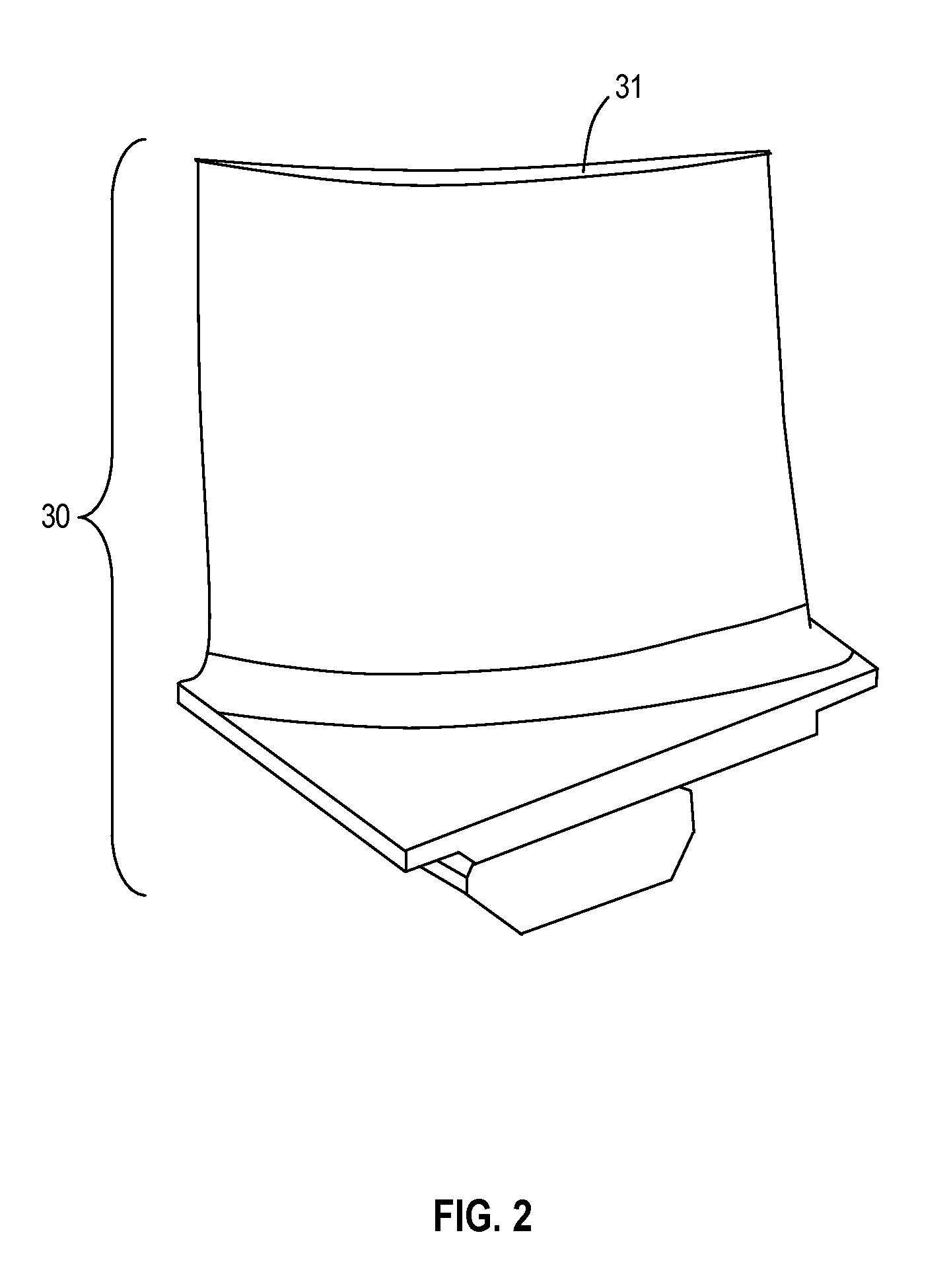
[0027]In operation, the blade 10 is subject to damage, especially tip and erosion damage from abrasive materials and / or foreign object impacts. The blade 10 in FIG. 1 is shown to include...


PUM

PropertyMeasurementUnit
Lengthaaaaaaaaaa
Electrical resistanceaaaaaaaaaa
Areaaaaaaaaaaa

Abstract

A turbine component repair apparatus includes: a first die having male and female halves for clamping a first section of a turbine blade with a platform and a root portion of an airfoil, the first die having a recess shaped to receive the root portion and retain a faying surface thereof in predetermined alignment; and a second die having male and female halves for clamping a repair section which defines a tip portion of the airfoil, the second die having a second recess shaped to receive the tip portion and retain a faying surface of the tip portion in predetermined alignment. The first and second dies have mating front faces configured to align their bottom surfaces in a common plane. A alignment device is removably attached to the second die to temporarily align the repair section in the absence of the male half of the second die.

Description

CROSS-REFERENCE TO RELATED APPLICATIONS[0001]This application claims the benefit of Provisional Patent Application No. 61 / 447,604, filed Feb. 28, 2011, currently pending.BACKGROUND OF THE INVENTION[0002]This invention relates generally to the repair of gas turbine engine components and more particularly to methods of attaching a repair section to a portion of an existing turbine component.[0003]A gas turbine engine includes a compressor that provides pressurized air to a combustor wherein the air is mixed with fuel and ignited for generating hot combustion gases. These gases flow downstream to a turbine section that extracts energy therefrom to power the compressor and provide useful work such as powering an aircraft in flight.[0004]During operation, turbine components, in particular the airfoils in the compressor, are exposed to a high velocity air stream that can lead to oxidation, corrosion, physical damage, and cracking from thermal cycling. Because turbine components are comple...

Claims


Application Information

Patent Timeline
IPC IPC(8): B23P6/00B23K37/04B25B11/00B23K11/00
CPCB23K11/002B23K11/02B23K11/14B23K37/0443Y10T29/49318B23P6/005F01D5/005F05D2230/80B23K2201/001Y10T29/49718Y10T29/4975B23K2101/001
Inventor KRIZANSKY, MICHAEL GARYPETERS, GARY R.SAM, HAI
Owner GENERAL ELECTRIC CO
Why Eureka
Try Eureka