Liquid ejecting apparatus

a technology of liquid ejector and ejector, which is applied in the direction of printing, other printing apparatus, etc., can solve the problems of slow down of satellite droplets, errors in operation, and difficulty in sure landing of satellites, and achieve the effect of preventing the influence of charging

Inactive Publication Date: 2012-08-30
SEIKO EPSON CORP
View PDF2 Cites 4 Cited by
  • Summary
  • Abstract
  • Description
  • Claims
  • Application Information

AI Technical Summary

Benefits of technology

[0012]An advantage of some of the aspects of the invention is to provide a liquid ejecting apparatus that can prevent the inside of the apparatus from being contaminated, by more reliably collecting mist.
[0014]According to the aspect of the invention, the ink ejection region of the support unit includes a conductive material and is set to have the same potential as nozzles, a nozzle formation surface, or ink in a pressure chamber and the droplet collecting unit is set to have a more negative polarity than the ink ejection region, such that liquid is ejected from the nozzles and positively charged, without an electric field between the nozzle formation surface and the support unit. Accordingly, mist created by separation of the liquid scattering toward the landing target is also positively charged, such that the mist is attracted by an electrostatic force from the droplet collecting unit, which is negatively charged, and landed and collected on the droplet collecting unit. Therefore, less mist adheres to the components (for example, a driving motor, a driving belt, and a linear scale) in the apparatus. As a result, a breakdown due to the adhering mist is suppressed and durability and reliability of the liquid ejecting apparatus are improved.
[0016]According to the aspect of the invention, since the ejection region of the support unit includes a conductive material and is set at the same potential as the nozzles, the nozzle formation surface, or the liquid in the pressure chamber and the droplet collecting unit is set to have a polarity opposite to the voltage applied to the driving electrode when the pressure generating unit is driven, liquid is ejected from the nozzles and charged with the same polarity as the voltage applied to the driving electrode, without an electric field between the nozzle formation surface and the support unit, and the liquid is separated while scattering toward the landing target, such that the mist is also charged with the same polarity as the voltage applied to the driving electrode. The mist is attracted by an electrostatic force from the droplet collecting unit charged with a polarity opposite to the voltage applied to the driving electrode, and landed and collected to the droplet collecting unit. Therefore, less mist adheres to the components (for example, a driving motor, a driving belt, and a linear scale) in the apparatus. As a result, a breakdown due to the adhering mist is suppressed and durability and reliability of the liquid ejecting apparatus are improved.
[0020]According to the aspect of the invention, since a voltage is applied to the absorbent material only when the nozzle formation surface of the liquid ejecting head and the droplet collecting unit are opposite each other, charging of the absorbent material does not influence the ejected liquid while the droplet ejecting head ejects droplets onto the landing target. Further, since a voltage is not applied to the absorbent material until the nozzle formation surface and the droplet collecting unit become opposite each other, mist is prevented from adhering to the end portions of the landing target in the width direction (head movement direction) while the liquid ejecting head moves toward the droplet collecting unit.
[0024]According to the aspect of the invention, it is possible to more reliably prevent the influence of charging of the droplet collecting unit on the ejected liquid while the liquid is ejected onto the landing target from the liquid ejecting head.

Problems solved by technology

Some or all of the satellite droplets rapidly decrease in speed due to viscous resistance of the air and change into mist, failing to reach the recording medium.
Accordingly, the satellite droplet changed into dust (ink dust) contaminates the inside of the apparatus and adheres to members that are easily charged, such as the recording head or the electric circuit, thereby causing errors in operation.
Further, the mist that does not adhere to the nozzle formation surface may adhere to other components of the printer which have different polarity from the mist and contaminate them.
Therefore, in the configuration of changing the polarity of the electrode at the timing of ejecting ink or the timing of separating the ink, it is more difficult to surely land the satellite droplets to the recording medium and scattering of the ink is influenced, thereby making the landing unstable.
As described above, in the configuration of the related art, it is difficult to reliably prevent the mist from adhering to the nozzle formation surface or the components of the printer.

Method used


Image

  • Liquid ejecting apparatus
  • Liquid ejecting apparatus
  • Liquid ejecting apparatus

Examples


Embodiment Construction

[0033]Embodiments of the invention are described hereafter with reference to the accompanying drawings. Although various limits are applied as detailed examples that are very suitable for the invention in the embodiment described below, the spirit of the invention is not limited thereto, if it is not stated to specifically limit the invention in the following description. Further, an ink jet type of recording apparatus (hereafter, printer) is exemplified, below as a liquid ejecting apparatus of the invention.

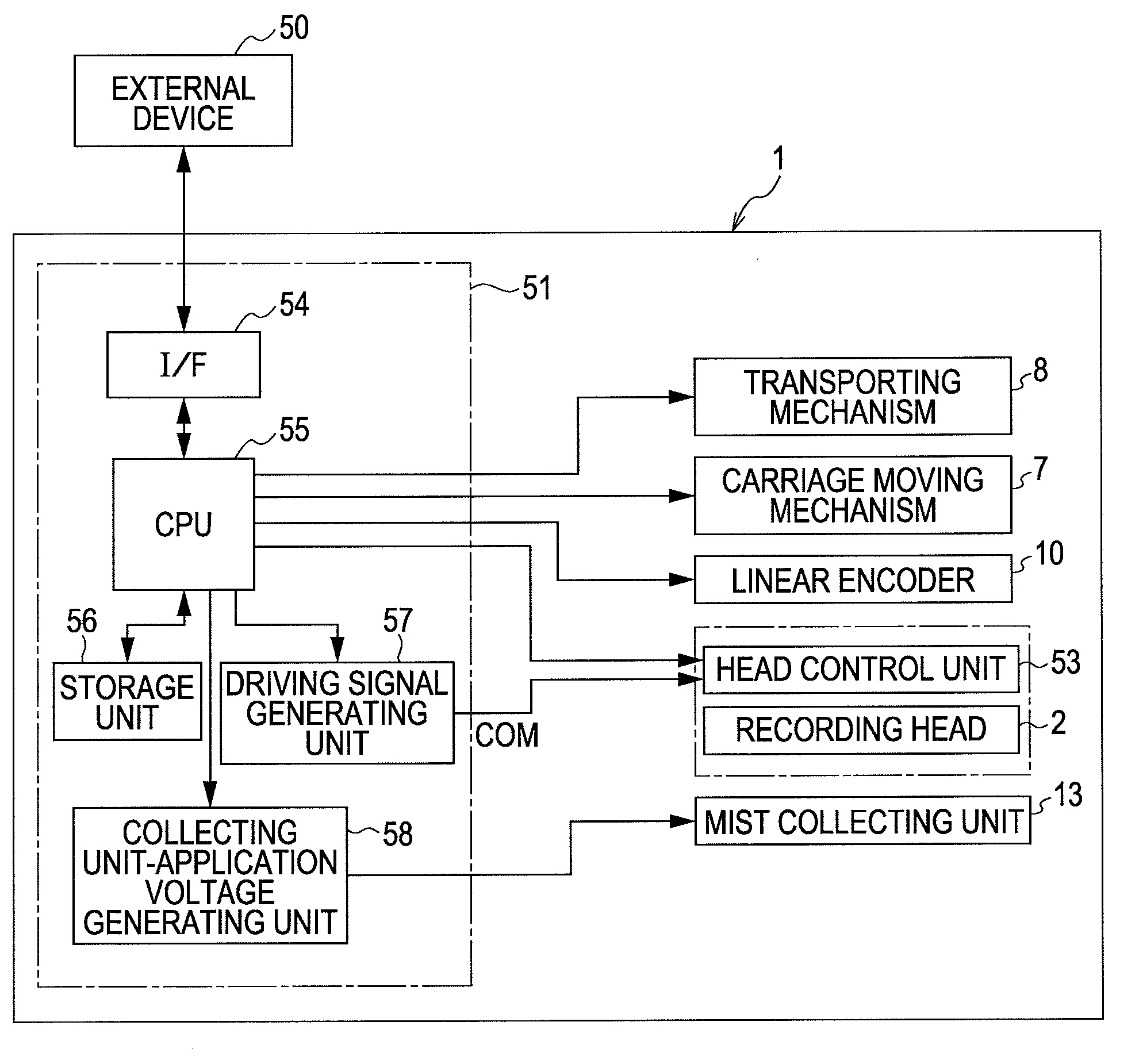
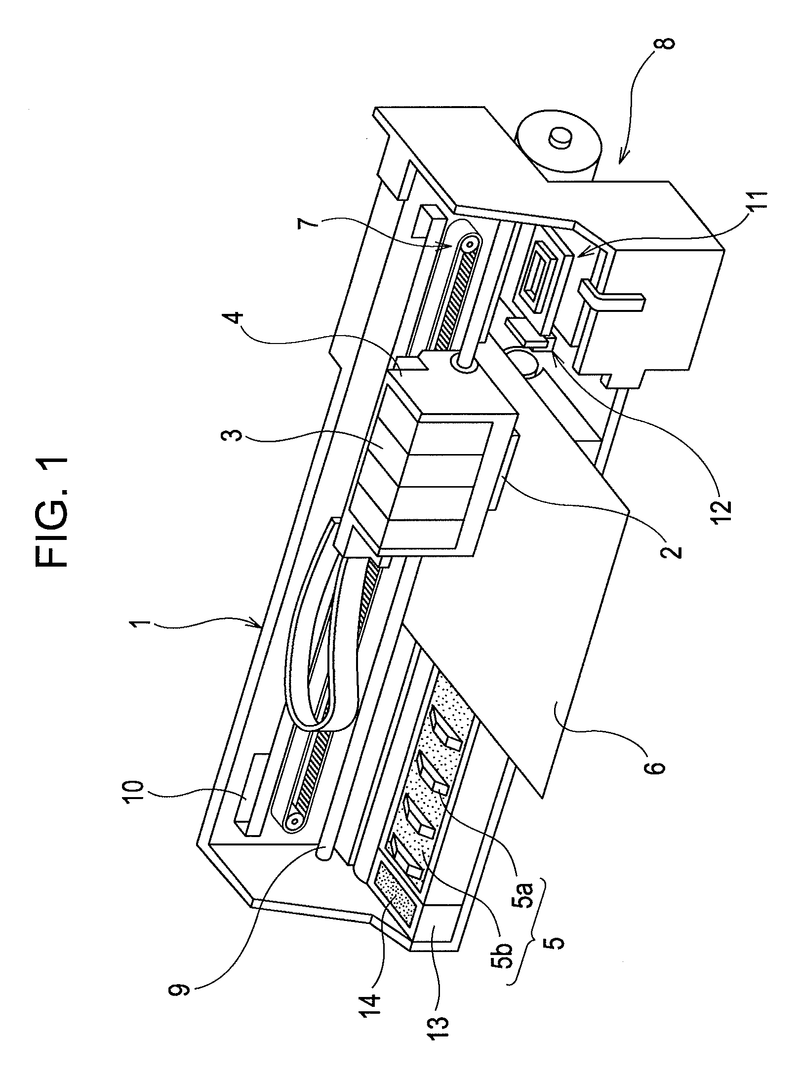
[0034]FIG. 1 is a perspective view showing the configuration of a printer 1. The printer 1 includes: a carriage 4 that is equipped with a recording head 2, which is a kind of liquid ejecting head, and detachably equipped with an ink cartridge 3 that is a kind of liquid supplier; a platen 5 that is disposed under the recording head 2 during recording; a carriage moving mechanism 7 that reciprocates the carriage 4 in the width direction of recording paper 6 (a kind of recording me...


PUM


Abstract

A liquid ejecting apparatus includes a mist collecting unit disposed outside an ink ejection region on a platen, where ink is ejected onto a recording paper from a recording head, in the movement direction of the recording head, the ink ejection region of the platen includes a conductive material and is set to have the same potential as nozzles, a nozzle formation surface, or ink in a pressure chamber, and the mist collecting unit is set to have a more negative polarity than the ink ejection region of the platen.

Description

BACKGROUND[0001]1. Technical Field[0002]The present invention relates to a liquid ejecting apparatus, such as an ink jet type recording apparatus, particularly a liquid ejecting apparatus that ejects liquid in a pressure chamber from nozzles by driving a pressure generating unit.[0003]2. Related Art[0004]A liquid ejecting apparatus is an apparatus equipped with a liquid ejecting head and ejecting various kinds of liquid from the ejecting head. For example, there are image recording apparatuses, such as an ink jet type printer or an ink jet type plotter, as the liquid ejecting apparatus, and recently, liquid ejecting apparatuses are used for various manufacturing apparatuses, using the feature that it is possible to accurately land a very small amount of ink to a predetermined position. For example, the liquid ejecting apparatus is used for a display manufacturing apparatus that manufactures a color filter, such as a liquid crystal display, an electrode forming apparatus that forms e...

Claims


Application Information

Patent Timeline
Patent Type & Authority Applications(United States)
IPC IPC(8): B41J29/38
CPCB41J2/1721B41J2/20B41J2002/1742B41J29/38B41J11/06
Inventor YAMADA, YOICHIKOBASHI, MASARUOKADA, TOSHIYA
Owner SEIKO EPSON CORP
Why Eureka
Try Eureka