Hybrid Circuit Breaker

Active Publication Date: 2012-08-30
ABB (SCHWEIZ) AG
View PDF12 Cites 44 Cited by
  • Summary
  • Abstract
  • Description
  • Claims
  • Application Information

AI Technical Summary

Benefits of technology

[0025]It is an object of the present invention to present a hybrid circuit breaker which works on the principle of keeping the voltage across a me

Problems solved by technology

Although the mechanical switch is not able to block the full voltage within the ho

Method used


Image

  • Hybrid Circuit Breaker
  • Hybrid Circuit Breaker
  • Hybrid Circuit Breaker

Examples


Embodiment Construction

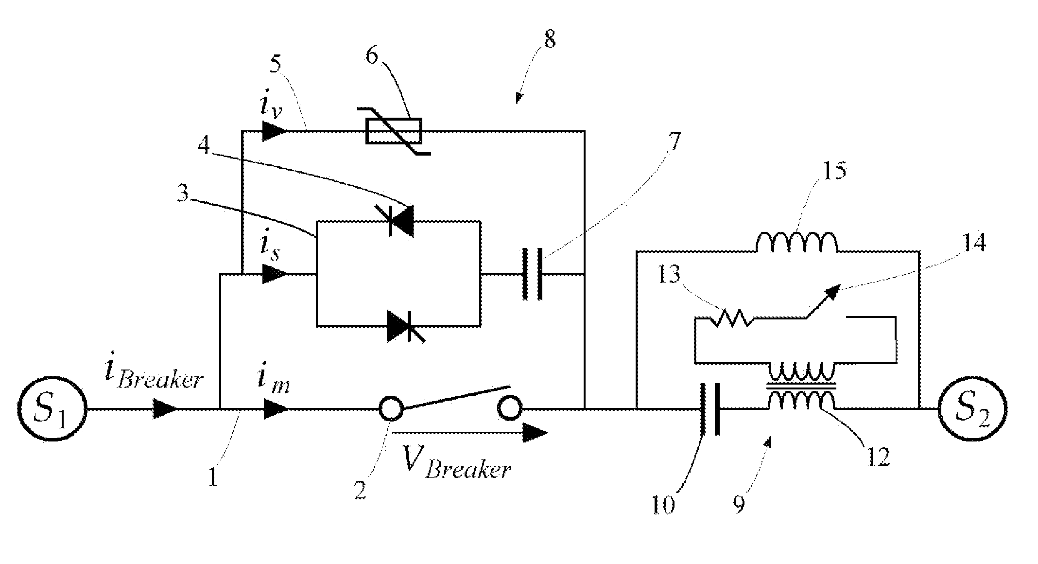
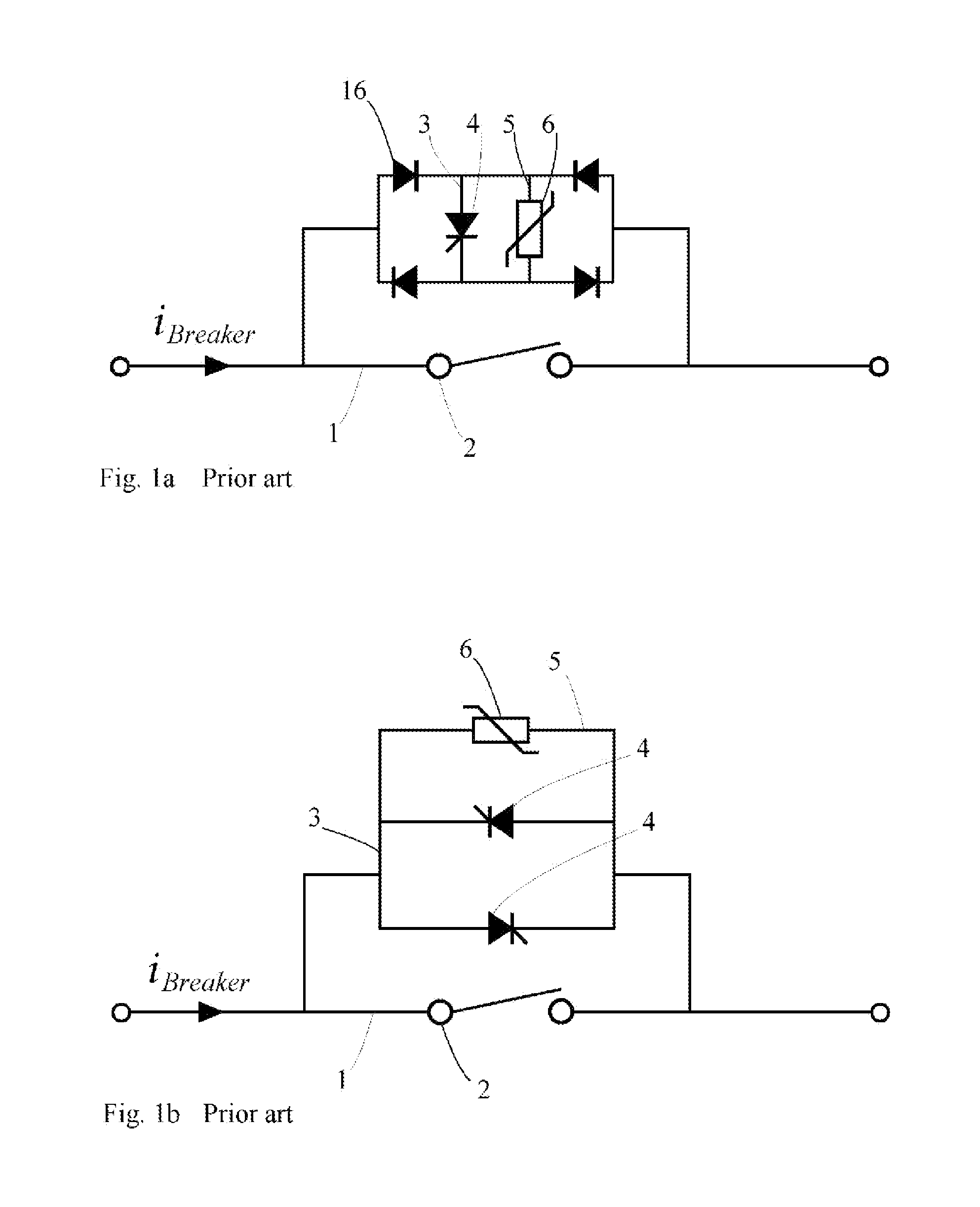
[0042]FIGS. 1a and 1b show two embodiments of hybrid circuit breakers of prior art, said embodiments also forming two examples of a main part of a first circuit of a circuit breaker according to the present invention, as will be seen later. In FIGS. 1a and 1b there are presented two different configurations of a bidirectional hybrid circuit breaker. In both embodiments, there is provided a main current path 1 with a mechanical switch element 2, a commutation path 3 parallel to the main path and comprising a controllable semiconductor switch element 4, as well as a dissipative circuit 5 arranged in parallel with the main path 1 and the commutation path 3 and provided with a suitable dissipative element 6, such as a varistor or the like. It is evident from these figures that a bidirectional ability of the circuit can be either achieved by a single controllable semiconductor switch element 4 along with four diodes 16 arranged in a bridge as known per se and as shown in FIG. 1a, or by t...


PUM


Abstract

A hybrid circuit breaker, including a first circuit that includes: a main current path which includes a mechanical switch element, a commutation path arranged in parallel with the main current path and including a controllable semi-conductor switch element. The breaker also includes a first capacitor provided in the commutation path in series with the controllable semi-conductor switch element, and a second circuit, arranged in series with the first circuit and including a second capacitor and an inductance-generating element arranged in series with each other.

Description

CROSS-REFERENCE TO RELATED APPLICATIONS[0001]The present application is a continuation of pending International patent application PCT / EP2009 / 063317 filed on Oct. 13, 2009 which designates the United States and the content of which is incorporated herein by reference.FIELD OF THE INVENTION[0002]The present invention relates to a hybrid circuit breaker, comprising a first circuit that comprises: a main current path which comprises a mechanical switch element and at least one commutation path arranged in parallel with the main current path and comprising a controllable semi-conductor switch element.[0003]The invention also relates to an electric power supply system comprising a hybrid circuit breaker according to the invention.[0004]The breaker is an electric current breaker. In particular, it may form part of an AC electric power system. In particular, it may form part of a medium or high voltage electric power system, medium or high voltage being referred to as a voltage of 400 V or...

Claims


Application Information

Patent Timeline
IPC IPC(8): H01H77/00
CPCH01H9/542H01H2009/544H01H2009/543H01H33/167
Inventor DEMETRIADES, GEORGIOSSHUKLA, ANSHUMAN
Owner ABB (SCHWEIZ) AG
Why Eureka
Try Eureka