Multiple use of a current transformer

a current transformer and multi-use technology, applied in the direction of ac-dc conversion, ac-electronic conversion, electrical apparatus, etc., can solve the problems of large space, additional losses, and the current transformer for measuring the winding current of the power converter needs significant spa

Active Publication Date: 2012-08-30
DELTA ELECTRONICS (THAILAND) PUBLIC CO LTD
View PDF2 Cites 26 Cited by
  • Summary
  • Abstract
  • Description
  • Claims
  • Application Information

AI Technical Summary

Benefits of technology

[0019]Hence, multiple use of the integrated current transformer of a power converter is provided in order to make optimal use of the additional space required by the integrated current transformer. Hence, depending on the application, the integrated current transformer is used to provide for optimal switching of synchronous rectifiers and/or to provide an auxiliary power supply in overload situations.
[0020]Preferably, the synchronous rectifier is closed for a first winding current at a later time than for a second winding current, wherein the first winding current is smaller than the second winding current. Alternatively, the synchronous rectifier is closed for the first winding current at an earlier time than for the second winding current. This has the advantage that closing of the synchronous rectifier can be adapted to various loads and/or parasitic effects, like inductive and/or capacitive loads and/or parasitic effects.
[0021]In a preferred embodiment, the synchronous rectifier is opened for a first winding current at an earlier time than fo

Problems solved by technology

Current sense resistors are cheap and often do not require much space, but cause additional losses.
Current transformers are relatively accurate and do not cause additional losses, but often need considerable space.
A current tran

Method used


Image

  • Multiple use of a current transformer
  • Multiple use of a current transformer
  • Multiple use of a current transformer

Examples


Embodiment Construction

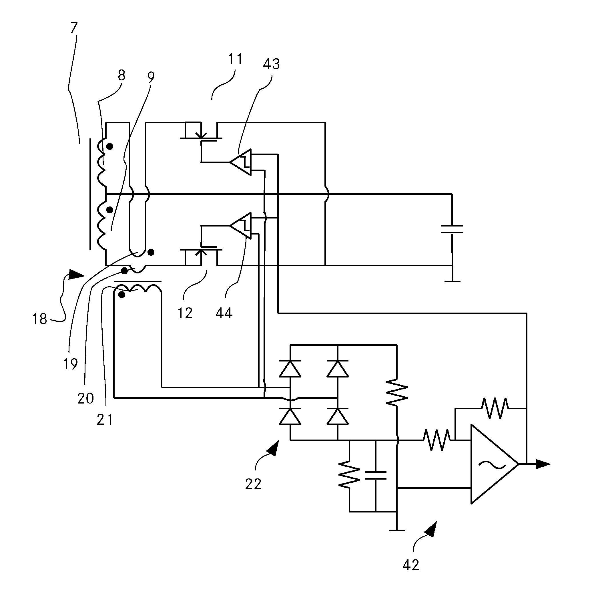
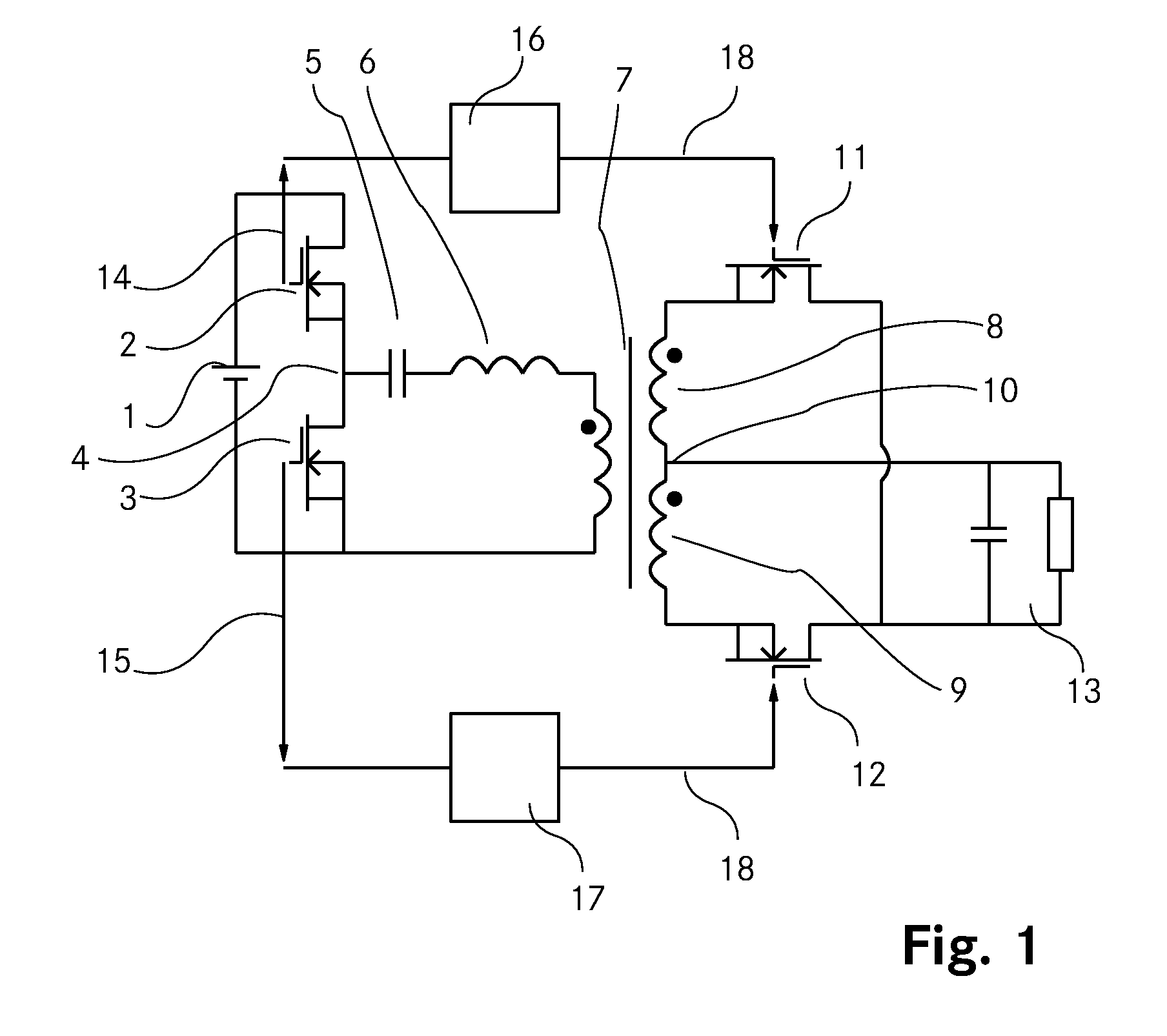
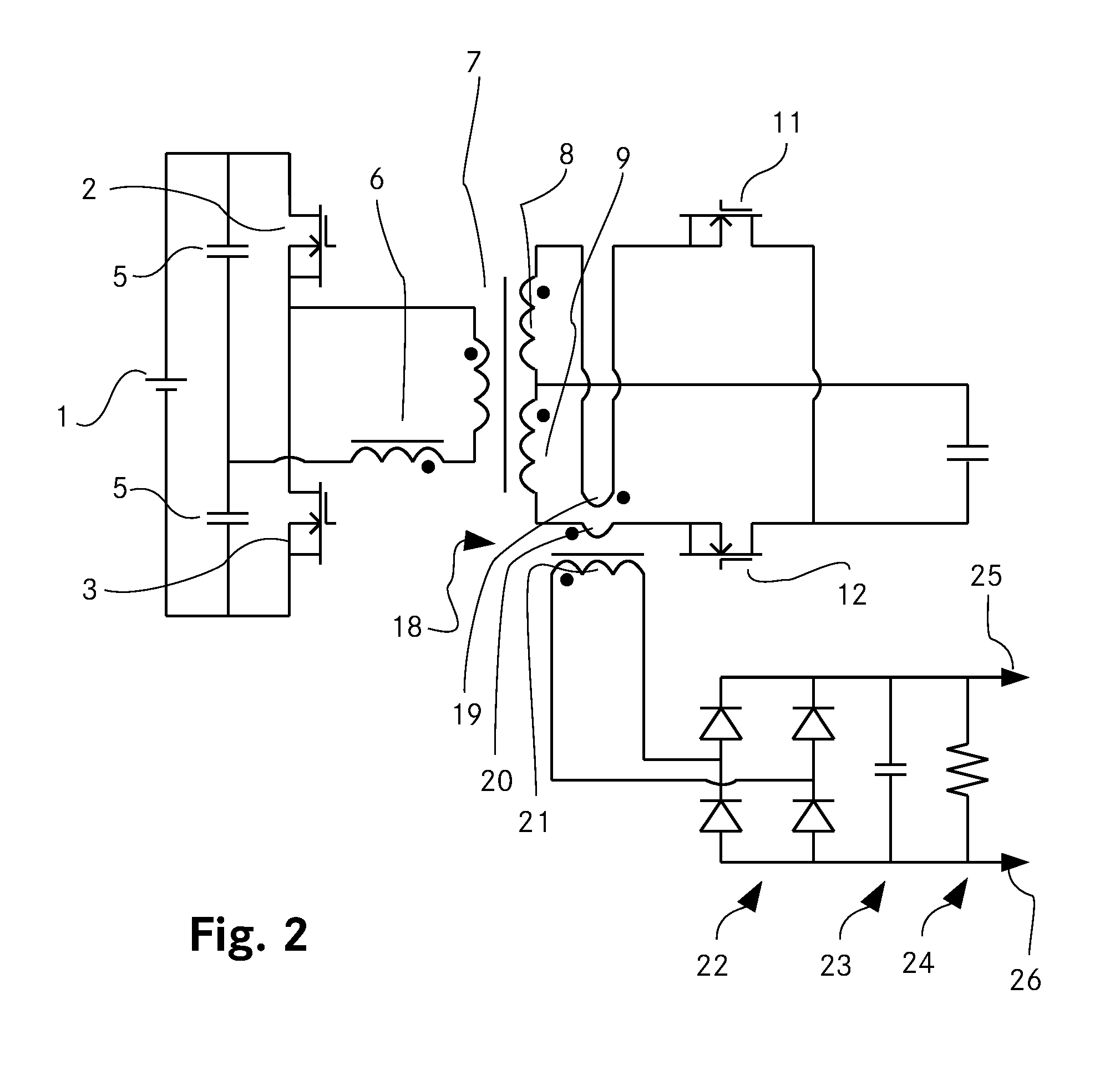
[0035]FIG. 1 shows a resonant converter according to the state of the art. A DC power source 1 (DC: direct current) is connected to a first switch 2 and a second switch 3, which are serially connected through primary tap 4. The first switch 2 and the second switch 3 are alternately opened and closed, whereby at primary tap 4 an oscillating voltage is generated. Primary tap 4 is connected through a capacitor 5 and an inductor 6 to the primary winding of converter transformer 7, which is also connected to one end of the DC power source 1. On the secondary side of converter transformer 7, a first secondary winding 8 and a second secondary winding 9 are serially connected through secondary tap 10. A first synchronous rectifier 11 is connected to the first secondary winding 8 and a second synchronous rectifier 12 is connected to the second secondary winding 9. The secondary tap 10 is connected to one end of load 13, whereas the other end of load 13 is connected to the first synchronous r...


PUM


Abstract

The invention relates to a power converter and a method for power conversion. A converter transformer with a primary winding and a secondary winding, an integrated current transformer and a synchronous rectifier are provided, wherein a controller is arranged in order to close respectively to open the synchronous rectifier depending on the measured winding current. The controller is arranged to close and/or to open the synchronous rectifier as a function of the winding current at a later and/or at an earlier time, whereby the time difference between the later and the earlier time is linearly dependent on the winding current difference, particularly in order to optimise a discharge process, and/or that an auxiliary supply circuit is arranged in order to provide auxiliary supply power, wherein the auxiliary supply circuit is arranged to derive auxiliary supply power from the integrated current transformer, in particular in overload situations.

Description

TECHNICAL FIELD[0001]The invention relates to a power converter comprising: a converter transformer with a primary winding and a secondary winding and an integrated current transformer arranged in order to measure a winding current of the converter transformer. The invention relates further to a method of power conversion, comprising the steps: converting electrical power with a converter transformer having a primary winding and a secondary winding and measuring a winding current of the converter transformer with an integrated current transformer.BACKGROUND ART[0002]In present power converters, particularly in resonant converters or switching power supplies, diode rectifiers or synchronous rectifiers are used in order to provide for a rectified output power. For high current applications, synchronous rectifiers are the preferred solution, because of their smaller power losses. A synchronous rectifier is a circuit that emulates a diode, allowing current to pass in one direction but n...

Claims


Application Information

Patent Timeline
IPC IPC(8): H02M7/217H02M1/00
CPCH02M3/33592Y02B70/1433Y02B70/1491H02M2001/0058Y02B70/1475H02M1/0058Y02B70/10
Inventor SPRINGETT, NIGEL IANBITSCH, WOLFGANG
Owner DELTA ELECTRONICS (THAILAND) PUBLIC CO LTD
Why Eureka
Try Eureka