Wind Turbine Rotor Blade with Varying Blade Depth

Inactive Publication Date: 2012-08-30
NORDEX ENERGY
View PDF3 Cites 1 Cited by
  • Summary
  • Abstract
  • Description
  • Claims
  • Application Information

AI Technical Summary

Benefits of technology

[0024]In one embodiment, the relative blade thickness varies in the vicinity of the outer longitudinal section and is greater at the blade root end of the outer longitudinal section than at the blade tip end of the outer longitudinal section. The relative blade thickness is the ratio of blade thickness and blade depth. In conventional rotor blades, the relative blade thickness in an external region is generally substantially constant and is often about 18%. With the invention, the relative blade thickness increases towards the blade root end of the outer longitudinal section, with an approximately constant blade depth. Compared to a conventional rotor blade, a greater relative blade thickness is achieved by reducing the blade depth in the outer longitudinal section towards the outer blade root end of the longitudinal section, despite an approximately constant absolute blade thickness. Thus, the height of a flexural torsion box, which imparts strength to the wind turbine rotor blade, need not be reduced or need not be reduced by much compared to a conventional wind turbine rotor blade. Sufficient strength can thus be achieved without making radical structural changes to the supporting structure of the wind turbine rotor blade.
[0025]In one embodiment, the relative blade thickness at the blade root end of the outer longitudinal section is greater by 10% or more than at the blade tip end of the outer longitudinal section. Experiments have shown that even a 10% or more, for example 30%, greater relative thickness does not significantly reduce the aerodynamic performance of the blade. The described positive effects on the achievable strength of the rotor blade therefore predominate.
[0026]In one embodiment, the blade depth decreases in a middle longitudinal section, which extends over 30% or less of the blade length, from 80% or more of the maximum blade depth to 40% or less of the maximum blade depth. The middle longitudinal section is at a distance from both the blade root and from the blade tip. The distance of the middle longitudinal section from the blade root can be, for example, 20% or more, preferably 30% or more of the blade length. The distance of the middle longitudinal section from the blade tip can be, for example, 20% or more, 30% or more or 40% or more of the blade length. In the middle longitudinal section there is a relatively rapid change of the blade depth compared with the blade depth profile of conventional rotor blades. This rapid transition means that the relatively narrow rotor blade in the outer longitudinal section changes within a relatively short longitudinal section into a relatively broad, inner longitudinal section. This relatively abrupt transition differs from the conventional blade d

Problems solved by technology

Furthermore, strength requirements and complex

Method used


Image

  • Wind Turbine Rotor Blade with Varying Blade Depth
  • Wind Turbine Rotor Blade with Varying Blade Depth
  • Wind Turbine Rotor Blade with Varying Blade Depth

Examples


Example

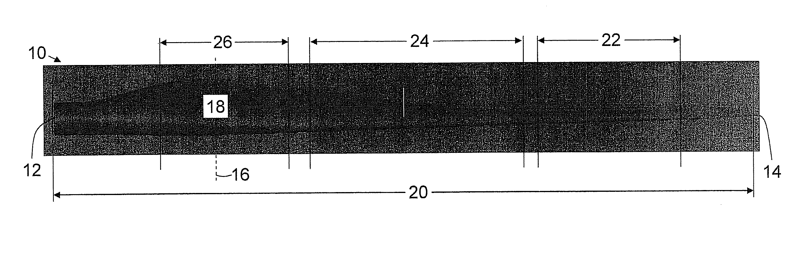
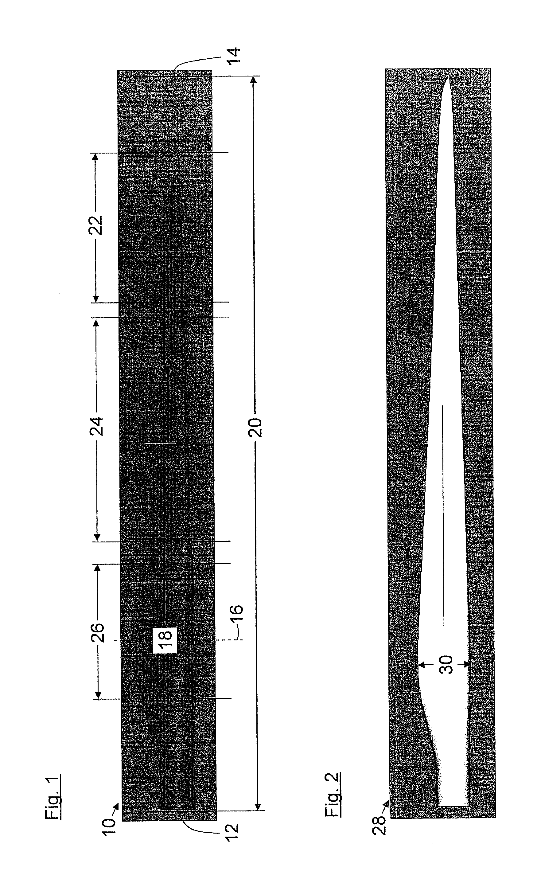
[0036]The wind turbine rotor blade 10 shown in FIG. 1 comprises a blade root 12 and a blade tip 14. At the blade root 12, the wind turbine rotor blade 10 has an essentially circular cross section and is configured for attachment to a rotor hub which is not shown. For example, for this purpose it comprises a flange that is also not shown in the figure. The circular cross section at the blade root 12 transitions into an aerodynamic profile with increasing distance from the blade root 12.

[0037]The rotor blade has a maximum blade depth 18 at a first longitudinal position 16. In the embodiment shown, this amounts to approximately 3.3 m. The blade length 20 of the rotor blade shown is approximately 42 m.

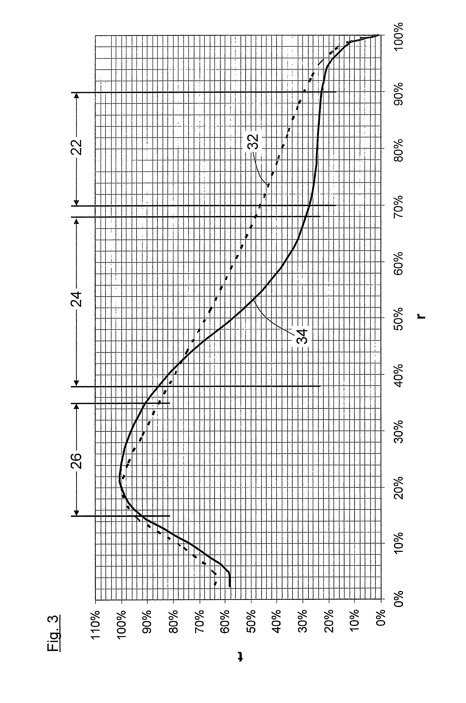
[0038]Furthermore, FIG. 1 shows an outer longitudinal section 22, a middle longitudinal section 24 and an inner longitudinal section 26. The outer longitudinal section 22 extends over 20% or more of the blade length 20. The blade depth is in the range from 20% to 30% of the maximum blade d...


PUM


Abstract

A wind turbine rotor blade has a blade root, a blade tip and a blade depth varying over the length of the rotor blade. The rotor blade has a maximum blade depth at a longitudinal position between the blade root and the blade tip. The blade depth in an outer longitudinal section, which extends over a length of 20% or more of the blade length, lies in a range from 20% to 30% of the maximum blade depth.

Description

CROSS REFERENCE TO RELATED APPLICATION[0001]This application claims priority of European patent application no. 11 001 581.5, filed Feb. 25, 2011, the entire content of which is incorporated herein by reference.FIELD OF THE INVENTION[0002]The invention relates to a wind turbine rotor blade having a blade root, a blade tip and a blade depth varying along the length of the rotor blade. The blade depth reaches a maximum depth at a longitudinal position between the blade root and the blade tip.BACKGROUND OF THE INVENTION[0003]The power captured by the rotor of a wind turbine from the wind depends on the aerodynamic characteristics of the rotor blades. Among other things, the aerodynamic profile, the angle of attack, the relative blade thickness and the blade depth of the rotor blade are important. A theoretically optimal blade depth profile can be found based on Betz's law and a series of simplifying assumptions. In this way one arrives at the following relationship for the optimal loca...

Claims


Application Information

Patent Timeline
IPC IPC(8): F03D1/06
CPCF03D1/0608Y02E10/721F05B2240/301Y02E10/72
Inventor FISCHER, GUNTER
Owner NORDEX ENERGY
Why Eureka
Try Eureka