Wire-cut electric discharge machine having function of detecting upper surface of workpiece

a wire-cut electric discharge machine and workpiece technology, applied in the direction of electrical circuits, electrical-based machining electrodes, manufacturing tools, etc., can solve the problems of reducing the machining speed, impractical to automatically adjust the nozzle gap, and the electric discharge between the wire electrode and the workpiece, so as to achieve accurate detecting the position

Active Publication Date: 2012-09-06
FANUC LTD
View PDF76 Cites 17 Cited by
  • Summary
  • Abstract
  • Description
  • Claims
  • Application Information

AI Technical Summary

Benefits of technology

[0021]According to the present invention, a wire-cut electric discharge machine that has a function of accurately detecting a position of an upper surface or a lower surface of a workpiece or positions of both of the upper and lower surfaces by relatively moving upper and lower wire guides and the workpiece and bringing a wire electrode into contact with the workpiece.

Problems solved by technology

In order to manually set a size of a gap between the end of the nozzle and the workpiece, such complicated operation is performed that an operator performs adjustment little by little by lowering a Z axis (vertical axis) in a running direction of a wire electrode little by little so that the gap has a designated fine value, while checking the gap with equipment such as a thickness gauge.
Accordingly, electric discharge between the wire electrode and the workpiece, which is required for machining a shape, is reduced, generating such problem that machining speed is reduced.
Therefore, it is impractical to automatically adjust a nozzle gap only depending on information of the thickness of a workpiece.
As a result, there are such problems that the wire-cut electric discharge machine becomes complicated and its cost is increased.
Therefore, it is difficult to accurately detect a position of the upper surface of the workpiece by using the technique disclosed in Japanese Patent Application Laid-Open No. 2005-111608.
However, in the case where the wire electrode is cut by an edged tool, the straightness of the wire electrode is not improved.
Consequently, there is a problem that the position of the upper surface of the workpiece cannot be accurately detected in the same way as the case where the wire electrode is melt-cut.

Method used


Image

  • Wire-cut electric discharge machine having function of detecting upper surface of workpiece
  • Wire-cut electric discharge machine having function of detecting upper surface of workpiece
  • Wire-cut electric discharge machine having function of detecting upper surface of workpiece

Examples


Embodiment Construction

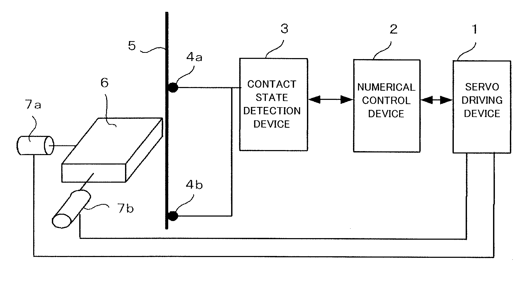
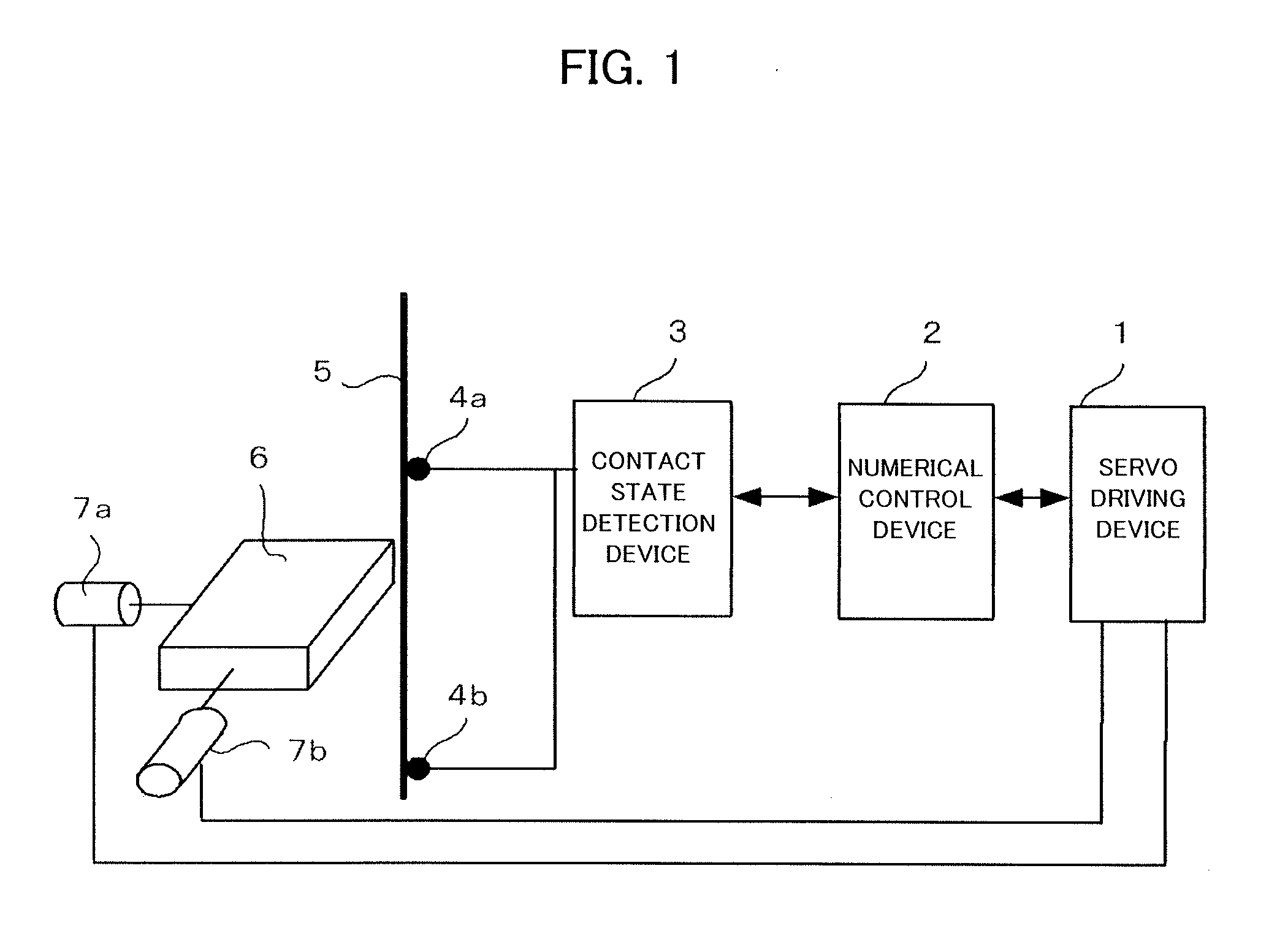
[0051]FIG. 1 is a schematic configuration diagram showing a wire-cut electric discharge machine having a function of detecting a position of a wire electrode 5 according to the present invention.

[0052]The wire-cut electric discharge machine shown in FIG. 1 includes a servo driving device 1, a numerical controller 2, and a contact state detection device 3. The servo driving device 1 drives servo motors 7a and 7b in accordance with a command from the numerical controller 2 so as to relatively move a workpiece 6 which is placed on a workpiece placing table (not shown) with respect to the wire electrode 5. The contact state detection device 3 detects contact of the wire electrode 5 and the workpiece 6 by using contact state detection pieces 4a and 4b. Here, the servo driving device 1, the numerical controller 2, and the contact state detection device 3 will be described later with reference to FIG. 28.

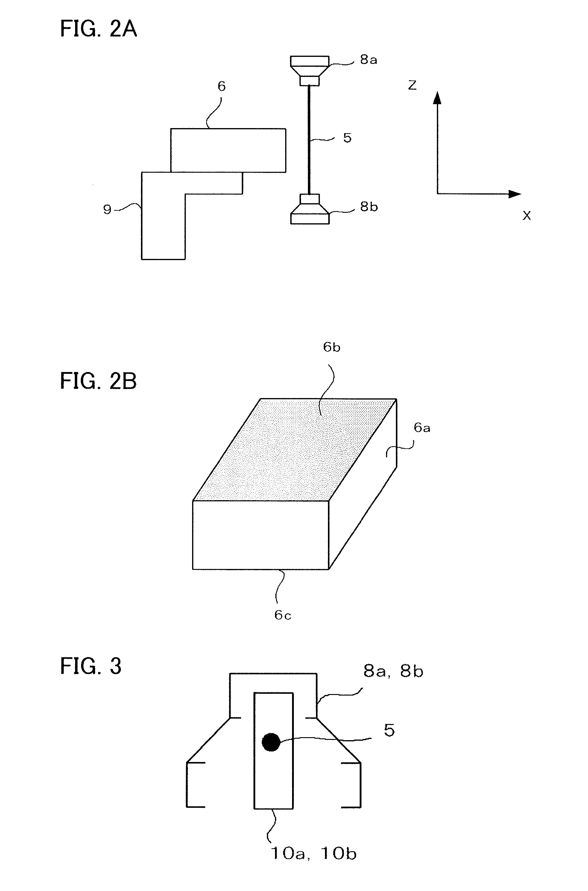
[0053]A positional relationship between the workpiece 6 placed on a workpiece placing ...


PUM

PropertyMeasurementUnit
diameteraaaaaaaaaa
thicknessaaaaaaaaaa
thicknessaaaaaaaaaa

Abstract

Upper and lower wire guides in a wire-cut electric discharge machine are moved until a wire electrode contacts with a workpiece, and after the contact, the upper and lower wire guides are moved backward to a position A which is away from the contact point at a fixed distance. Then, the upper wire guide is moved until the wire electrode contacts with the workpiece and the upper wire guide is returned to the position A. Subsequently, the lower wire guide is moved until the wire electrode contacts with the workpiece and the lower wide guide is returned to the position A. A coordinate value on the position where the wire electrode contacts with the workpiece is calculated by using position detection values which are obtained in the above respective steps, and board thickness is calculated from the coordinate value.

Description

BACKGROUND OF THE INVENTION[0001]1. Field of the Invention[0002]The present invention relates to a wire-cut electric discharge machine which has a function of detecting upper and lower surfaces of a workpiece when machining the workpiece.[0003]2. Description of the Related Art[0004]A wire-cut electric discharge machine applies a voltage between poles of a wire electrode and a workpiece to generate electric discharge and at the same time, changes relative positions of the wire electrode to the workpiece, thus machining the workpiece in a desired form.[0005]Concerning a machining result of a workpiece, dimensional accuracy, verticality, and angle accuracy are commonly required. In order to obtain a desired machining result, it is necessary to accurately obtain relative positions of a wire electrode to a workpiece. These relative positions are accurately obtained on the basis of a relationship of relative vertical positions of the wire electrode to the workpiece. In order to solve the ...

Claims


Application Information

Patent Timeline
Patent Type & Authority Applications(United States)
IPC IPC(8): B23H1/02
CPCB23H7/065B23H2500/20B23H7/20
Inventor KAWAHARA, AKIYOSHIFURUKAWA, HIROYUKI
Owner FANUC LTD
Why Eureka
Try Eureka