
Semiconductor device comprising a die seal having an integrated alignment mark

Inactive Publication Date: 2012-09-06
GLOBALFOUNDRIES INC
View PDF3 Cites 8 Cited by
  • Summary
  • Abstract
  • Description
  • Claims
  • Application Information

AI Technical Summary

Benefits of technology

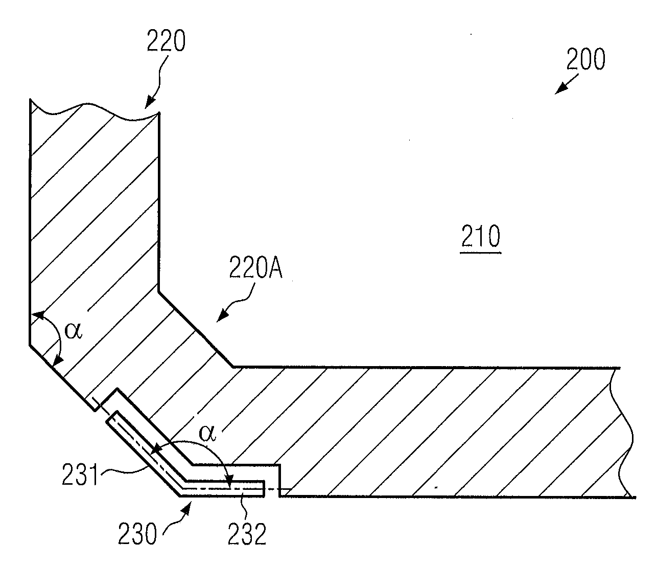
[0016]Generally, the present disclosure provides semiconductor devices in which a required mechanical stability of a die seal may be preserved, while at the same time an appropriate alignment mark may be positioned so as to enable superior monitoring of the inner die region without compromising alignment accuracy and requiring increased scribe lane widths. To this end, the alignment mark may be provided with an appropriate shape with respect to a top view thereof so as to be positioned at least partially within and, in some illustrative embodiments disclosed herein, within the die seal region, however, without unduly affecting the mechanical stability thereof. For this purpose, the alignment mark may be positioned at or close to a corner portion of the die seal region in which generally an increased width is available, wherein the alignment mark may be provided with an appropriately shaped elongated marked portion having a significantly reduced width compared to the remaining die seal region. Furthermore, the geometric characteristics of the alignment mark may be selected such that an appropriate alignment process may be performed, wherein, if desired, different geometric configurations may be selected for the various alignment portions and / or for the various alignment marks in order to provide additional information that may be used during the alignment process.

Problems solved by technology

It is, therefore, the goal of semiconductor manufacturers to reduce the consumption of raw materials and consumables while at the same time improve process tool utilization, since, in modern semiconductor facilities, equipment is required which is extremely cost intensive and represents the dominant part of the total production costs.
In sophisticated semiconductor devices, not only the circuit elements formed in and above a corresponding semiconductor layer require thorough monitoring, but also the metallization system of the semiconductor device is of high complexity, thereby also requiring sophisticated process and material monitoring techniques.
Providing a moderately high number of stacked metallization layers is associated with a plurality of process-related challenges, thereby requiring efficient monitoring and control strategies.
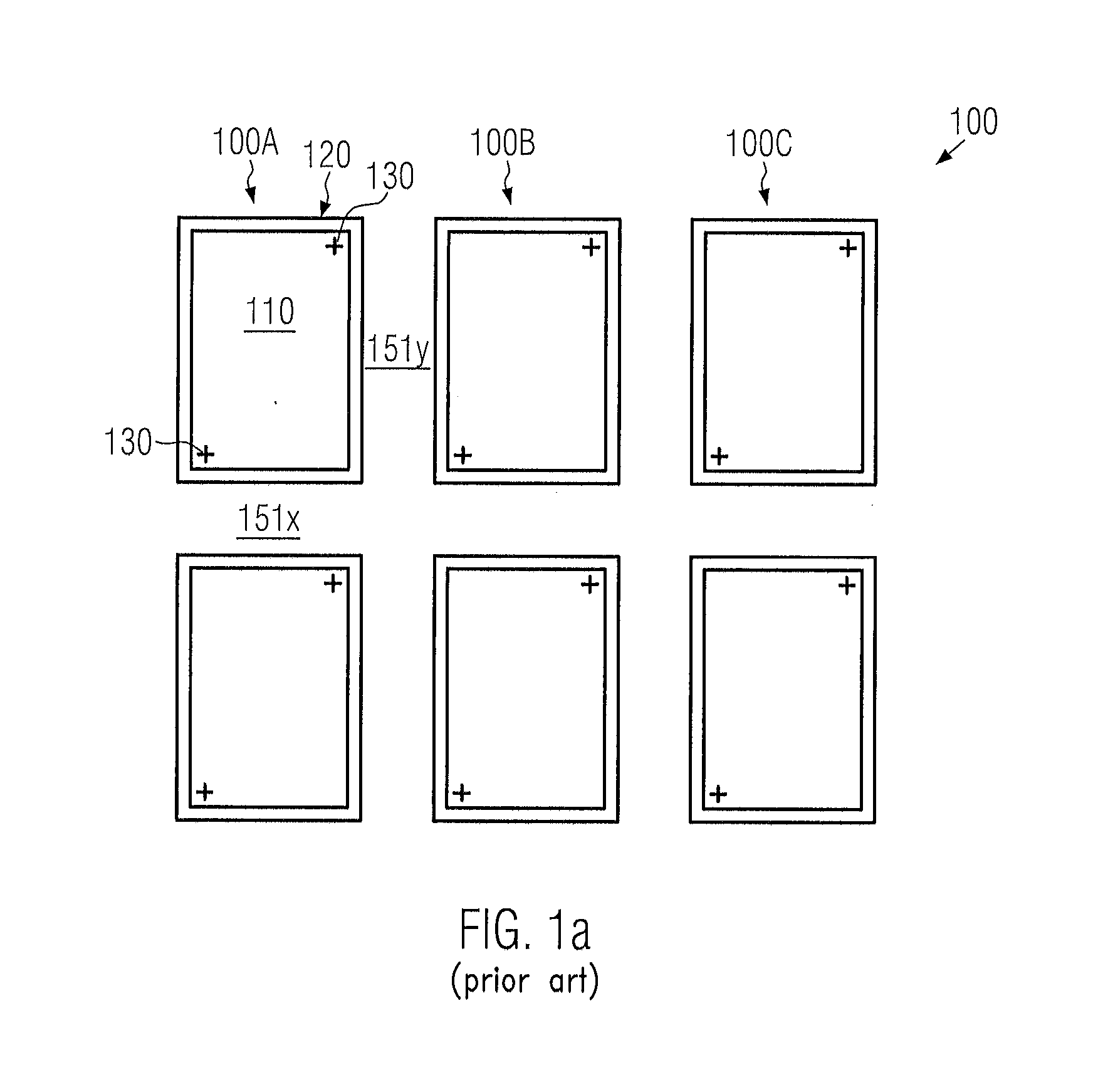
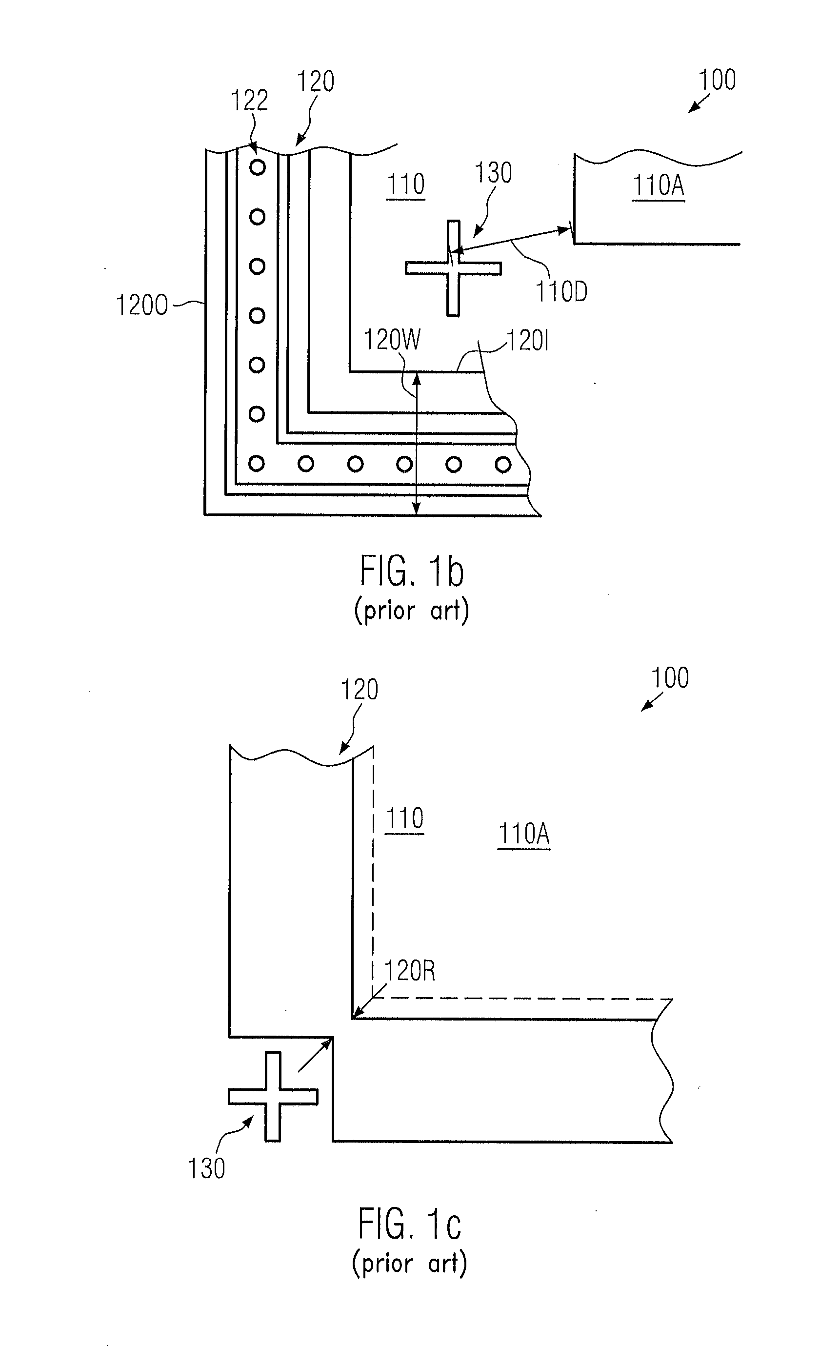
It turns out, however, that the provision of a mechanically stable die seal and alignment marks, which may allow superior accessibility of the actual die region, may not be compatible with conventional designs and strategies, as will be described in more detail with reference to FIGS. 1a-1c.
Consequently, upon dicing the substrate, significant mechanical damage may be caused unless the corresponding scribe lines are increased in width, thereby significantly reducing the overall process throughput.

Method used


Image

  • Semiconductor device comprising a die seal having an integrated alignment mark
  • Semiconductor device comprising a die seal having an integrated alignment mark
  • Semiconductor device comprising a die seal having an integrated alignment mark

Examples


Embodiment Construction

[0027]Various illustrative embodiments of the invention are described below. In the interest of clarity, not all features of an actual implementation are described in this specification. It will of course be appreciated that in the development of any such actual embodiment, numerous implementation-specific decisions must be made to achieve the developers' specific goals, such as compliance with system-related and business-related constraints, which will vary from one implementation to another. Moreover, it will be appreciated that such a development effort might be complex and time-consuming, but would nevertheless be a routine undertaking for those of ordinary skill in the art having the benefit of this disclosure.

[0028]The present subject matter will now be described with reference to the attached figures. Various structures, systems and devices are schematically depicted in the drawings for purposes of explanation only and so as to not obscure the present disclosure with details ...


PUM


Abstract

In semiconductor devices, the alignment mark for performing alignment processes of measurement tools and the like may be positioned within the die seal area on the basis of a geometric configuration, which still preserves mechanical integrity of the die seal without compromising the spatial information encoded into the alignment marks. For example, L-shaped alignment marks may be provided at one or more corners of the die seal area.

Description

BACKGROUND OF THE INVENTION[0001]1. Field of the Invention[0002]Generally, the present disclosure relates to the field of integrated circuits, and, more particularly, to alignment marks and die seal structures formed in the metallization system of semiconductor devices.[0003]2. Description of the Related Art[0004]Today's global market forces manufacturers of mass products to offer high quality products at a low price. It is thus important to improve yield and process efficiency and, thus, minimize production costs. This holds especially true in the field of semiconductor fabrication, since here it is essential to combine cutting edge technology with mass production techniques. It is, therefore, the goal of semiconductor manufacturers to reduce the consumption of raw materials and consumables while at the same time improve process tool utilization, since, in modern semiconductor facilities, equipment is required which is extremely cost intensive and represents the dominant part of th...

Claims


Application Information

Patent Timeline
IPC IPC(8): H01L23/544
CPCH01L23/544H01L23/585H01L2223/5442H01L2223/54426H01L2224/81121H01L2924/0002H01L2223/54453H01L2924/00H01L21/0273H01L21/68H01L24/80
Inventor LEHR, MATTHIAS
Owner GLOBALFOUNDRIES INC
Learn More