Electrostatic discharge device and method for manufacturing the same

a technology of electrostatic discharge and discharge device, which is applied in the direction of cell components, emergency protective arrangements for limiting excess voltage/current, shielding materials, etc., can solve the problems of reducing material strength and transparency, changing colour, and frequently undesirable changes,

Active Publication Date: 2012-09-06
CONDALIGN AS
View PDF13 Cites 13 Cited by
  • Summary
  • Abstract
  • Description
  • Claims
  • Application Information

AI Technical Summary

Benefits of technology

[0059]Another element of the invention is that the amount of conductive particles may be below the percolation threshold. This has several advantages in that mixtures having only small amounts of conductive particles are less prone to macrophase separation and are thereby easier to store. Also the mechanical strength of the anisotropic conductive film can be increased if the amount of particles can be reduced. For UV cured films the curing process is more effective when the amount of shielding particles is lower. Likewise the transparency of a film can be increased if the amount of particles can be reduced. A lower amount of conductive particles is also a cost-saving element.

Problems solved by technology

These changes are frequently undesirable, e.g. a decrease in material strength and transparency and change in colour.
Mixed systems have limited lifetime and must be re-mixed prior to use.
A common problem is that a film or layer even when manufactured to a uniform thickness, will have non-uniform conductivity because the filler material will not distribute evenly.
The problem is well-known in polymer physics and stems from the mutual incompatibilities of filler materials and polymer matrix, which means that only small amount of fillers can be mixed with the matrix to lead to the stable mixture.
Moreover, the mixing process applied for higher filler quantities must be so vigorous that the filler particles may get broken.

Method used


Image

  • Electrostatic discharge device and method for manufacturing the same
  • Electrostatic discharge device and method for manufacturing the same
  • Electrostatic discharge device and method for manufacturing the same

Examples


example 1

[0093]This example concerns the preparation of a mixture of conductive particles and polymer matrix which is a thermally cured polymer adhesive. It also shows the conductivity as a function of particle load and how the step-like increase in conductivity with increasing particle load can be explained by formation of conductive paths between particles when the contacts are formed with increased particle fraction.

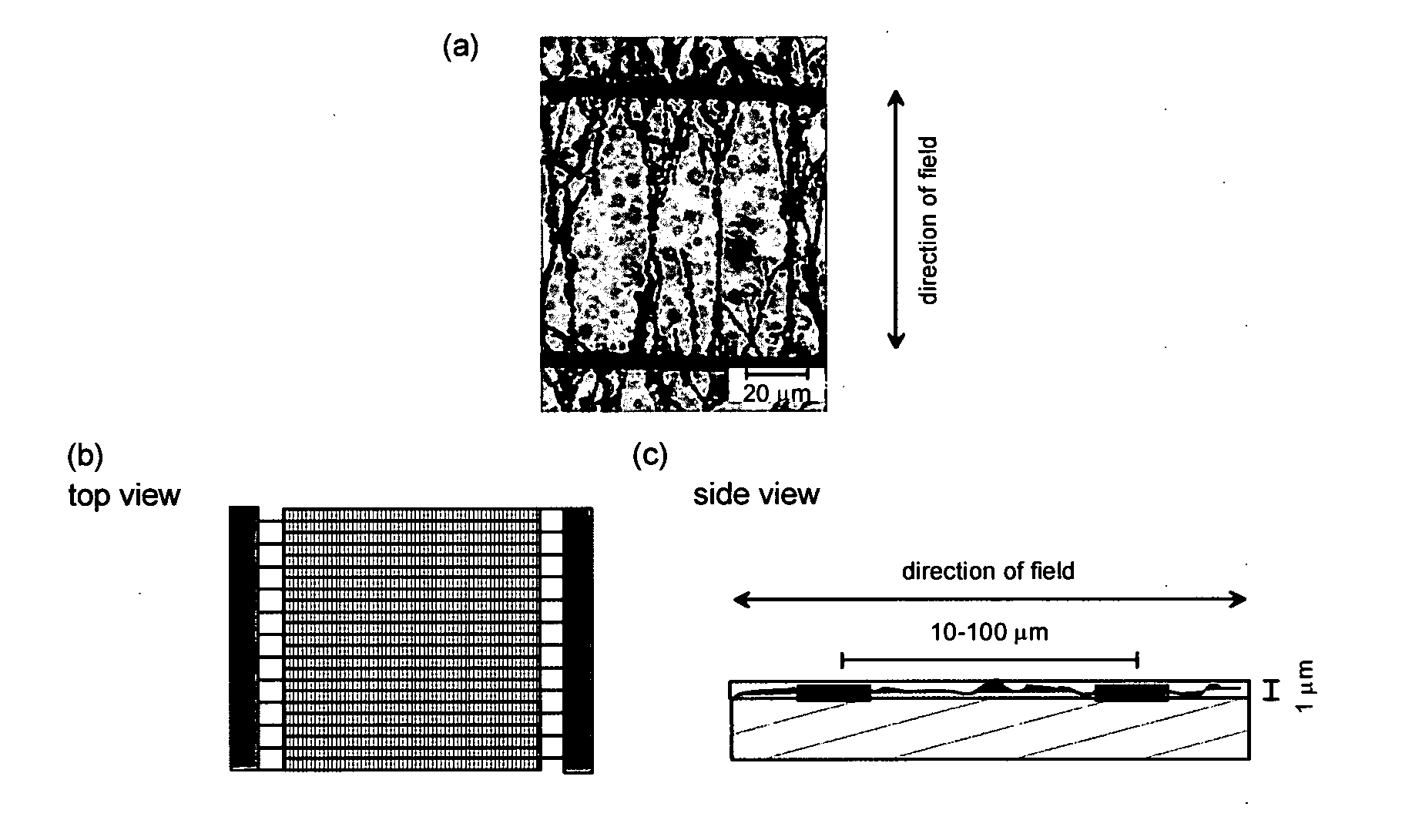
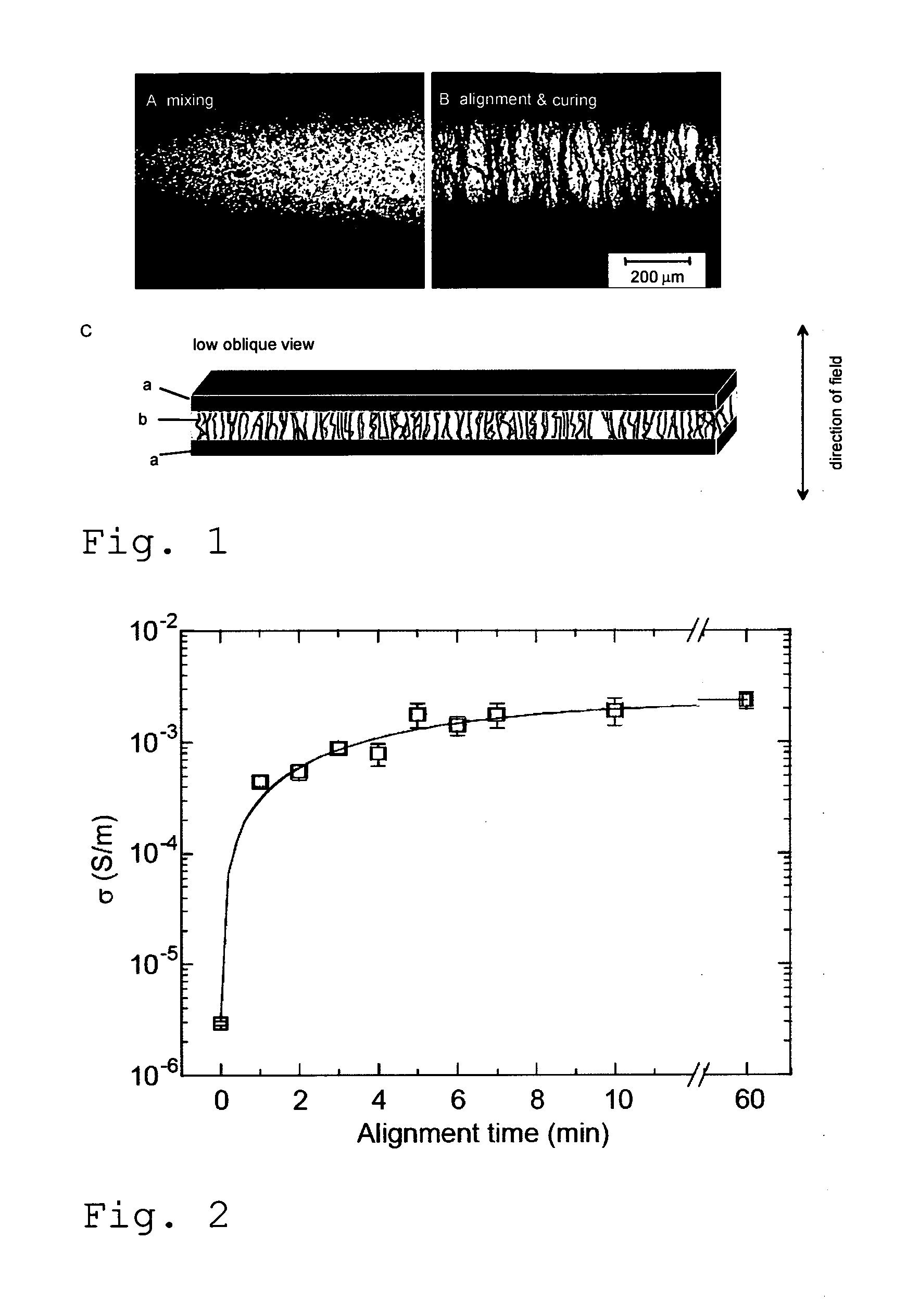
[0094]This example concerns moreover the preparation of the same mixture when the particle load is low, for example 10 times less than the observed percolation threshold, the limit where the isotropic non-aligned mixture is not conductive; as well as the alignment of this mixture using electric field so that the aligned particles form conductive paths resulting in a conductive material, whose conductivity is directional, for example below the percolation threshold of non-aligned material. The example, moreover, shows the change of the viscosity of the resulting material obtain...

example 2

[0105]This example concerns versatile choice of alignment conditions and illustrates how the present invention can be employed not only with electrodes connected to the orientation material but also with electrodes electrically isolated from the material.

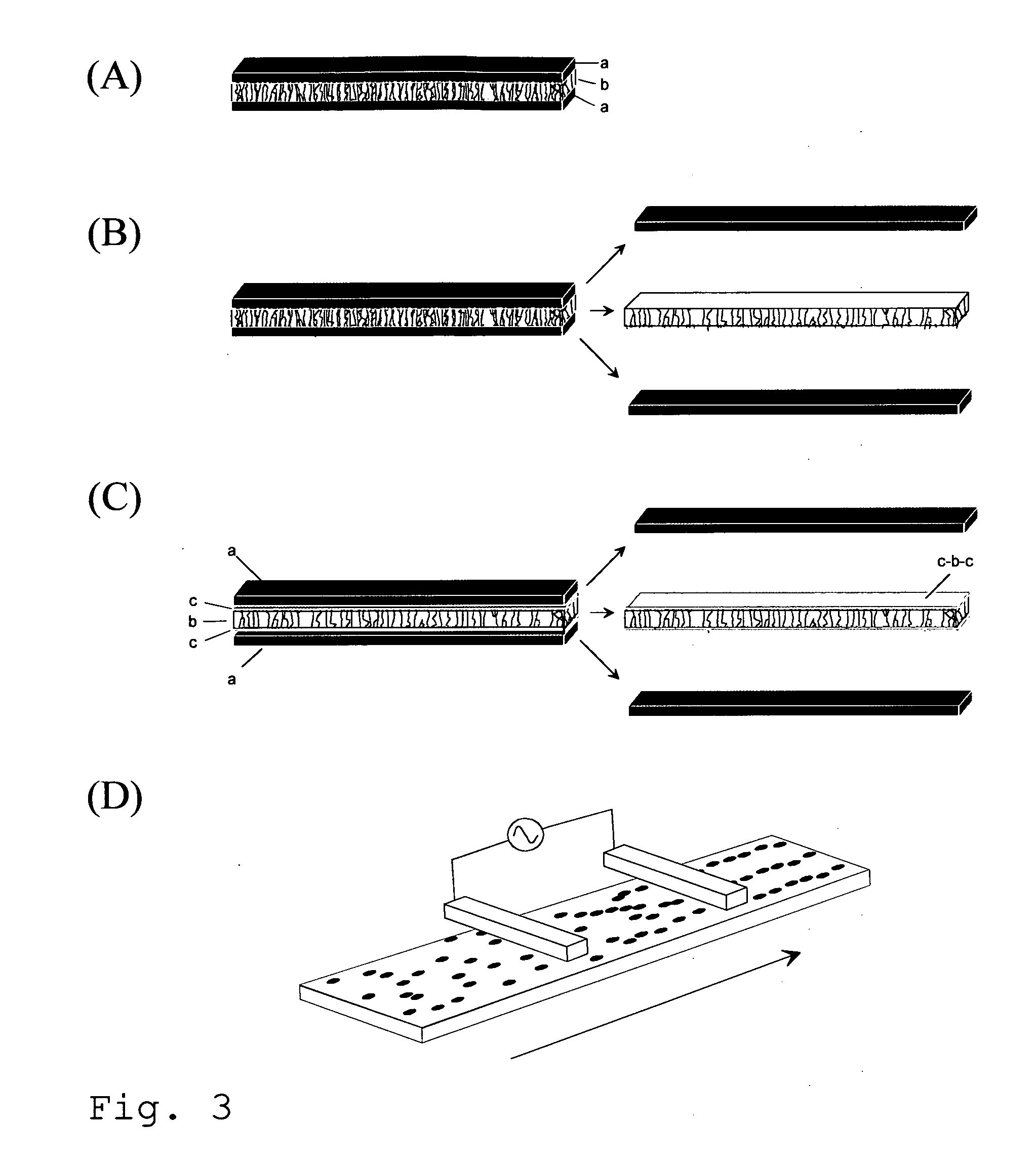
[0106]The procedure was otherwise similar to that in example 1, but instead of having material directly connected to the alignment electrodes, the electrodes were electrically disconnected from the material by an insulating layer, for example by 0.127 mm Kapton® foils. Alignment occurred exactly as in example 1.

[0107]This procedure allows removal of electrodes after alignment and thus freestanding aligned film even in the case where the matrix is adhesive. The alignment also occurs if the electrodes do not touch the material and so the alignment can be performed from a distance. When the material and electrodes are moved, continuous or stepwise, with respect to each others during the alignment, this allows continuous alignment proce...

example 3

[0108]This example concerns the applicability of the alignment method, the use of alignment for particular application of UV-curing. This emphasises the benefit of low particle fraction which makes the material better transparent for UV light for curing.

[0109]The procedure was otherwise similar to that in example 1 or 2 but the thermally cured polymer matrix was replaced by UV-curable Dymax Ultra Light-Weld® 3094 adhesive and the curing step was done by the UV-light with the wavelength 300-500 nm.

[0110]FIG. 4 illustrates the alignment of 0.2 vol-% CNC dispersion in out-of-plane geometry. The mixture was formed following the guideline of example 1 (FIG. 4a) but spread on the alignment electrode using RK Print Paint Applicator that uses a moving bird applicator to level the adhesive layer to the predetermined thickness (the idea is schematically illustrated in FIG. 4b). This admixture was aligned following the method outlined in example 2 but the upper electrode was not in contact wit...


PUM

PropertyMeasurementUnit
electric fieldaaaaaaaaaa
thicknessaaaaaaaaaa
thicknessaaaaaaaaaa

Abstract

The invention is achieved by applying a layer of the mixture that contains polymer and conductive particles over a first surface, when the mixture has a first viscosity that allows the conductive particles to rearrange within the layer. An electric field is applied over the layer, so that a number of the conductive particles are aligned with the field and thereafter the viscosity of the layer is changed to a second, higher viscosity, in order to mechanically stabilise the layer. This leads to a stable layer with enhanced and anisotropic conductivity that can be used in the manufacture of ESD devices.

Description

TECHNICAL FIELD[0001]The invention concerns conductive and dissipative electrostatic discharge (ESD) devices, also known as antistatic devices and a method for manufacturing them, using conductive paths of low-cost particles in a curable nonconductive matrix.BACKGROUND OF THE INVENTION[0002]When two objects of dissimilar materials are rubbed together electrons are transferred from one material to the other through the process of triboelectrification. The objects become statically charged with one material accumulating positive charge and the other material accumulating negative charge. The process of safely discharging electrostatic charges or preventing or minimizing their occurrence, e.g. in a manufacturing or workplace environment, is accomplished through ESD devices. These devices have the effect of reducing static electricity charges on a person's body or equipment, for example to prevent fires and explosions when working with flammable liquids and gases, or to prevent damage t...

Claims


Application Information

Patent Timeline
Patent Type & Authority Applications(United States)
IPC IPC(8): H02H9/04B05D3/14B05D5/12
CPCH05K9/0079H01B1/24Y02E60/10B81B1/00B82B3/00H05F1/00B05D1/005B05D1/40B05D3/14B05D2601/20H01G9/0003H01M4/628H05F3/025
Inventor SVASAND, ELDRIDBUCHANAN, MARKKNAPPILA, MATTIHELGESEN, GEIRMAELAND, ARNULF
Owner CONDALIGN AS
Why Eureka
Try Eureka