Syringe with integrated cannula

Active Publication Date: 2012-09-06
ANESTAWEB
View PDF7 Cites 30 Cited by
  • Summary
  • Abstract
  • Description
  • Claims
  • Application Information

AI Technical Summary

Benefits of technology

[0025]It is yet another object of the present invention to provide a syringe assembly configured to receive an adapter hub that converts the syringe assembly into a standard Luer-type syringe, providing legacy compatibility with needle hubs and other attaching devices presently available in the field.
[0026]It is yet another object of this present invention to provide a syringe a

Problems solved by technology

Although accomplishing the goal of delivering medication into the human body in a sterile manner, these early glass syringes were relatively cumbersome and crude in design.
For one, the technician must remove and replace the draw-needle hub with the injection-needle hub which can compromise overall sterility of the procedure while also exposing the technician and patient to the risk of needle sticks from the draw-needle hub that is set aside.
Additionally, confusion could occur between the two needle hubs, causing the technician to inadvertently inject the patient using the large-bore and presumably less sterile draw needle.
The ov

Method used


Image

  • Syringe with integrated cannula
  • Syringe with integrated cannula
  • Syringe with integrated cannula

Examples


Embodiment Construction

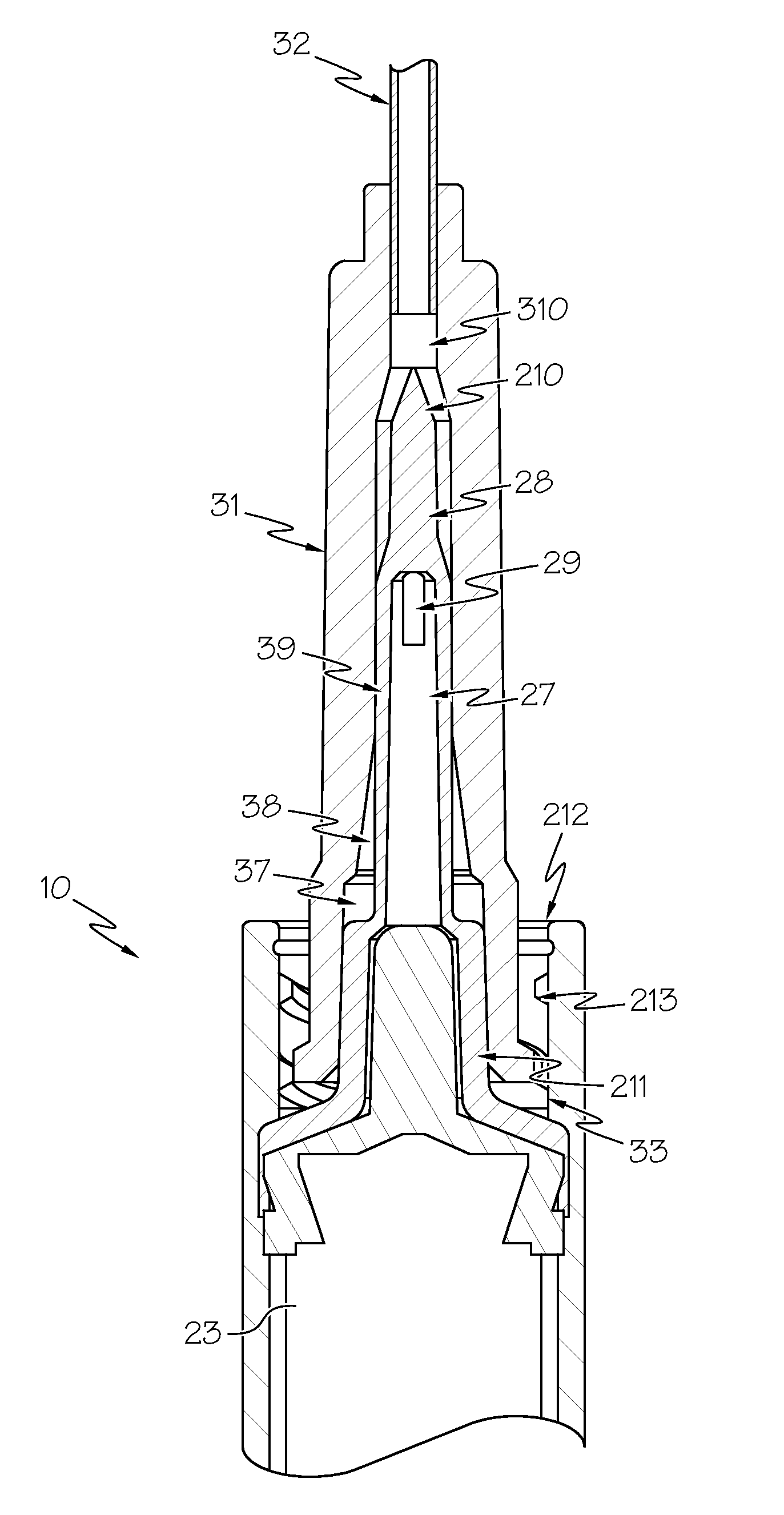
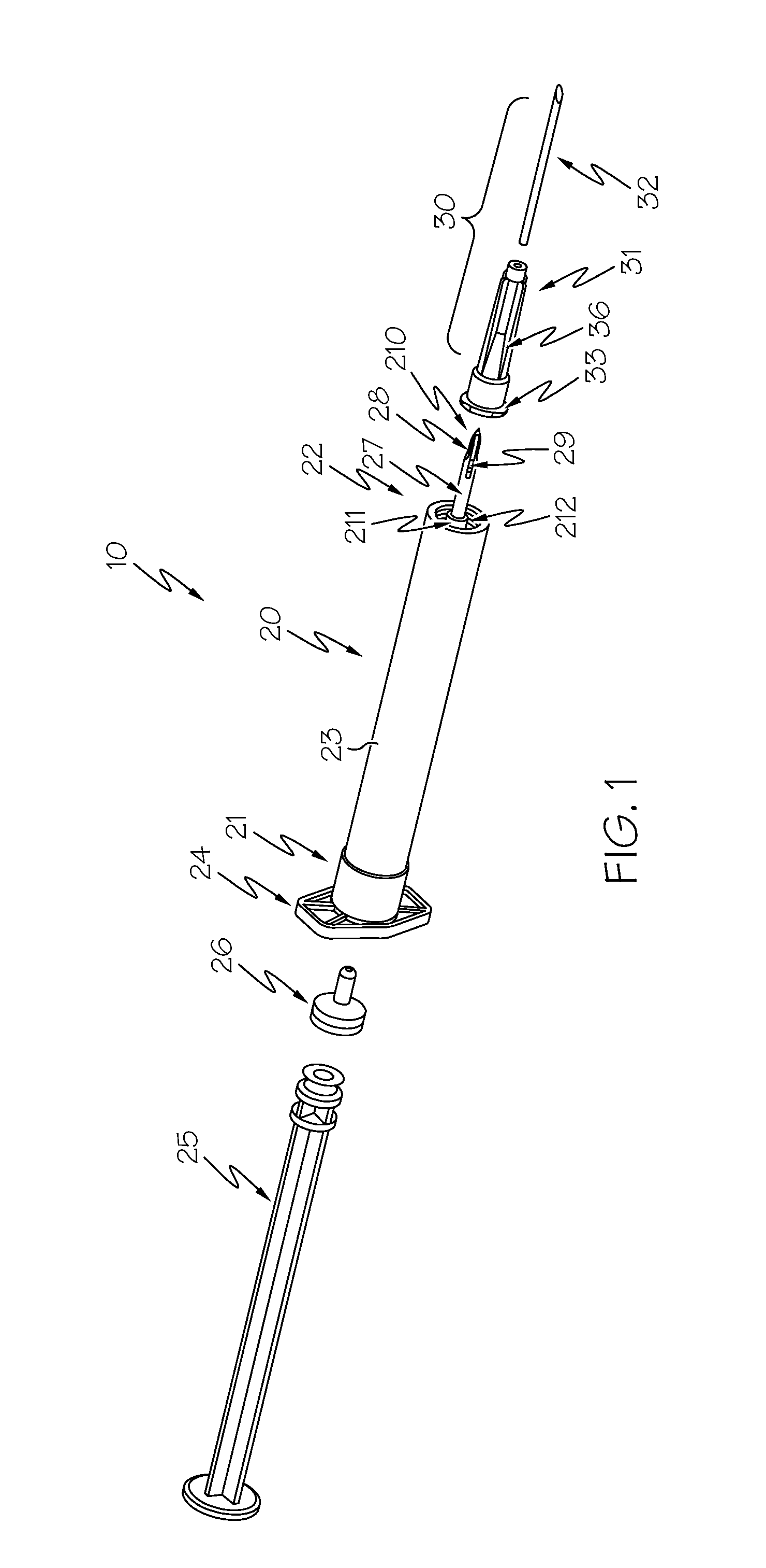
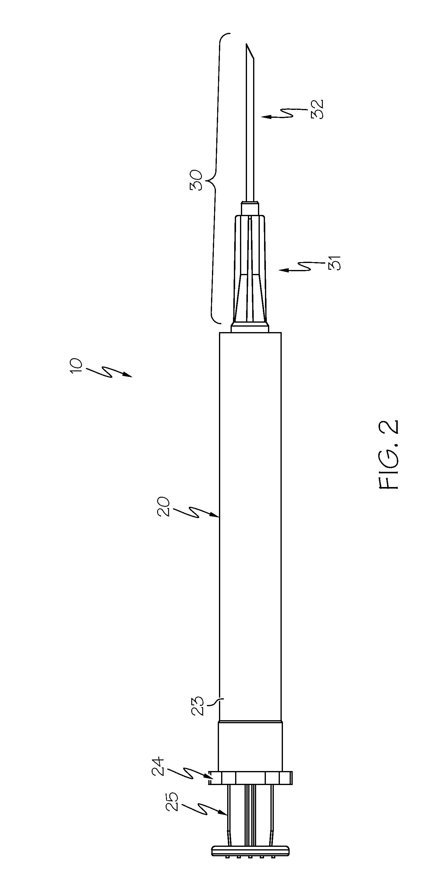
[0042]With reference to FIGS. 1-4, shown is one embodiment of the syringe 10 of the present invention. Shown is an elongated tubular syringe barrel 20 having an open proximal end 21 and a partially closed distal end 22. The interior surface of barrel 20 delimits a chamber 23. Disposed at proximal end 21 is a finger guard 24 which extends laterally from the outer surface of barrel 20. Plunger 25 is slidingly received in the chamber 23 and is configured to reciprocate therein. Plunger tip 26 may be disposed at the distal end of plunger 25, providing a liquid-tight sealed engagement with chamber 23. The finger guard 24 is configured to assist with compressing plunger 25 into chamber 23 during use.

[0043]Extending from and integrated into the distal end 22 of barrel 20 is a cannula 27. Cannula 27 delimits a hollow lumen that is in fluid flow communication with chamber 23 of barrel 20. As more clearly shown in FIG. 7, in some embodiments, cannula 27 includes bi-lateral fluid flow channels...


PUM


Abstract

A syringe assembly includes a tubular barrel having an open proximal end, a distal end, and an internal a fluid retaining chamber. A plunger is slidingly received in the chamber and is configured to draw fluid into and expel fluid from the chamber. A hollow projection extends from the distal end of the barrel and a cannula extends from the hollow projection. The cannula may have a spiked tip, a transverse orifice, and longitudinally disposed bi-lateral fluid flow channels. The cannula is adapted to penetrate the seal of a medical access point, such as a medicine vial, IV port, or catheter port. A receiving collar including one or more male threads surrounds the hollow projection and the cannula and is adapted to releasably engage a needle hub. The needle hub has an internal cavity configured to matingly receive and cover the cannula.

Description

CROSS REFERENCE TO RELATED APPLICATIONS[0001]This application claims the benefit of U.S. Provisional Application No. 61 / 464,349, filed Mar. 4, 2011.STATEMENT REGARDING FEDERALLY SPONSORED RESEARCH OR DEVELOPMENT[0002]N / ABACKGROUND OF THE INVENTION[0003]1. Field of the Invention[0004]The present invention generally relates to medical devices for the administration of medicines, drugs, and other therapeutic materials and more specifically to a syringe having an integrated cannula and components related thereto.[0005]2. Description of Related Art[0006]In the early stages of syringe use, medical professionals relied on reusable glass hypodermic syringes and needles which were boiled for sterility after each use. Although accomplishing the goal of delivering medication into the human body in a sterile manner, these early glass syringes were relatively cumbersome and crude in design. As early as the 1950's, the idea for a disposable syringe came to pass. With the development of new materi...

Claims


Application Information

Patent Timeline
IPC IPC(8): A61M5/31A61M5/32A61M5/315
CPCA61M5/1782A61M5/31515A61M5/3291A61M2005/3201A61M5/347A61M5/502A61M5/345A61B17/3417A61B2017/3454
Inventor GREEN, CHRISTOPHER
Owner ANESTAWEB
Why Eureka
Try Eureka