Surgical Device and Surgical Method

a surgical device and surgical method technology, applied in the field of surgical instruments and surgical methods, can solve the problems of difficult to determine the diameter of the sulcus and the capsular bag from the outside of the eye, and the white-to-white corneal diameter is not a reliable indicator, so as to achieve accurate alignment and high precision

Active Publication Date: 2012-09-06
CARL ZEISS MEDITEC AG
View PDF3 Cites 56 Cited by
  • Summary
  • Abstract
  • Description
  • Claims
  • Application Information

AI Technical Summary

Benefits of technology

[0024]Accordingly, it is possible to insert the distal end portion of the tube into the interior of the eye at a portion of the cornea, which is distant from the main axis of the eye. Through the range of the bending angle, the position of the portion of the cornea, through which the distal end portion of the tube is inserted, may be optimized. Also, it is possible for the user to adjust the position of the distal end portion within the eye under observation of a microscope. The optical axis of the microscope may be aligned substantially parallel to the main axis of the eye. Thereby, it is possible for the user to accurately align with the main axis of the eye, the portion of the longitudinal axis, which is within the transparent tubular section. Thereby, structures like the ciliary sulcus, the anterior chamber angle of the capsular bag are arranged within the measurement range

Problems solved by technology

However, the white-to-white corneal diameter is not a reliable indicator for the angle diameter of the anterior chamber and the sulcus diameter, also referred to as sulcus-to-sulcus diameter, of the posterior chamber.

Method used


Image

  • Surgical Device and Surgical Method
  • Surgical Device and Surgical Method
  • Surgical Device and Surgical Method

Examples


Embodiment Construction

[0069]In the exemplary embodiments described below, components that are alike in function and structure are designated as far as possible by alike reference numerals. Therefore, to understand the features of the individual components of a specific embodiment, the descriptions of other embodiments and of the summary should be referred to.

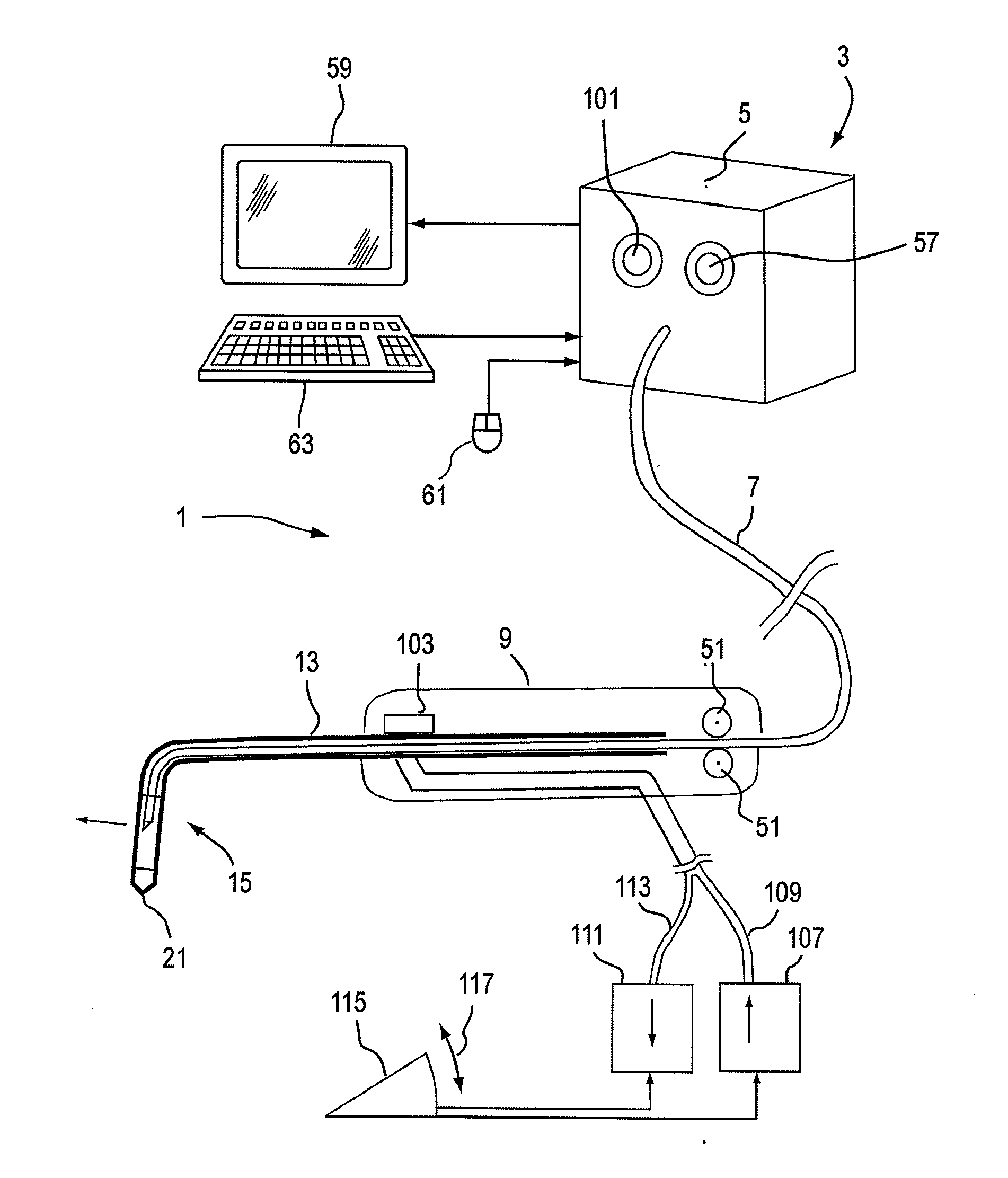
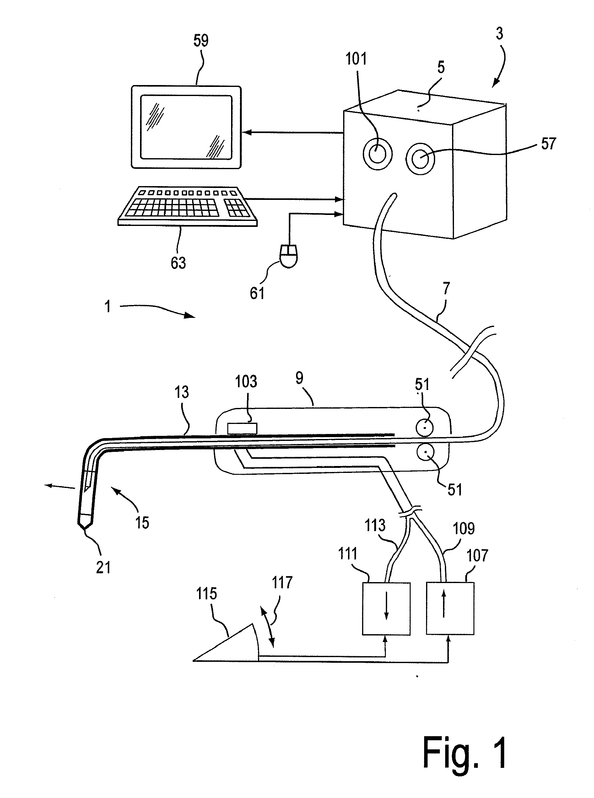
[0070]FIG. 1 is a schematic illustration of a surgical instrument system 1 according to an exemplary embodiment. The surgical instrument system 1 comprises an optical coherence tomography (OCT) apparatus 3 including an optical interferometer received in a housing 5 (not shown in detail in FIG. 1). The interferometer includes a reference arm and a probe arm. The probe arm is provided and extended by an optical fiber 7. The optical fiber 7 comprises a fiber core (not illustrated in FIG. 1) for transmitting OCT measuring light of the OCT apparatus 3. The fiber 7 extends through a hand piece 9 of a hand tool. The hand tool is manipulated by a surgeon. Th...


PUM


Abstract

A surgical instrument system for ophthalmic surgery in an eye is provided, comprising: an OCT apparatus including an interferometer; an optical fiber coupled to the OCT apparatus and extending a probe arm of the interferometer; a hand tool comprising: a hand piece, a tube extending away from the hand piece and comprising a distal end portion having a longitudinal axis, wherein a distal portion of the optical fiber is received within the tube; a beam emitter coupled to a tip end of the optical fiber and configured to emit an OCT measuring beam into an emission direction; and an actuator configured to change the emission direction of the OCT measuring beam relative to a tip end of the distal end portion.

Description

CROSS-REFERENCES TO RELATED APPLICATIONS[0001]The present application is a bypass-continuation of international patent application PCT / EP2010 / 006935, which claims priority of Patent Application No. EP 09 014 235 filed on Nov. 13, 2009 with the European Patent Office and entitled “Surgical Device and Surgical Method” and of Provisional Patent Application No. 61 / 261,249, filed on Nov. 13, 2009 in the United States of America, the contents of both documents is hereby incorporated by reference in their entirety.FIELD[0002]The invention relates to surgical devices and surgical methods in general. In particular, the invention relates to a surgical instrument system and a surgical method for performing cataract surgery.BACKGROUND[0003]In a cataract surgery, a phacoemulsification needle is inserted into the capsular bag of a patient's eye through the cornea and the anterior chamber. Ultrasonic energy is supplied to the needle to emulsify the crystal lens of the eye. Emulsified pieces of the...

Claims


Application Information

Patent Timeline
IPC IPC(8): A61B18/20
CPCA61B3/1005A61F9/00745A61B3/102
Inventor HAUGER, CHRISTOPH
Owner CARL ZEISS MEDITEC AG
Why Eureka
Try Eureka