Apparatus And Method For Damping Vibration In A Drill String

a drill string and vibration damping technology, applied in the field of underground drilling, can solve the problems of one or more threaded joints between the drill string sections to uncouple, the drill string will over-speed, and the drill string has no effective method for damping vibration, so as to reduce the torsional vibration of the drill string and limit the maximum angular velocity of the drill string

Active Publication Date: 2012-09-13
APS TECH
View PDF5 Cites 80 Cited by
  • Summary
  • Abstract
  • Description
  • Claims
  • Application Information

AI Technical Summary

Benefits of technology

[0007]The current invention provides an apparatus and method for reducing drill string torsional vibration, including torsional vibration due to stickslip. According to the invention, a torsional damping force (i.e., reverse torque) can be applied to the drill string, for example, by interacting with the borehole wall or by inducing internal rotational fluid resistance, and thereby limiting the maximum angular velocity of the drill string.

Problems solved by technology

Often, the bit will over-speed as the drill string unwinds.
Another possible outcome is the when the slip ends, a rebound motion will cause part of the drill string to rotate counterclockwise, which may cause one or more of the threaded joints between the drill string sections to uncouple.
Unfortunately, although the existence of harmful torsional vibration, and in particular “stick-slip”, can be detected, there is currently no effective method for damping such vibration.

Method used


Image

  • Apparatus And Method For Damping Vibration In A Drill String
  • Apparatus And Method For Damping Vibration In A Drill String
  • Apparatus And Method For Damping Vibration In A Drill String

Examples


first embodiment

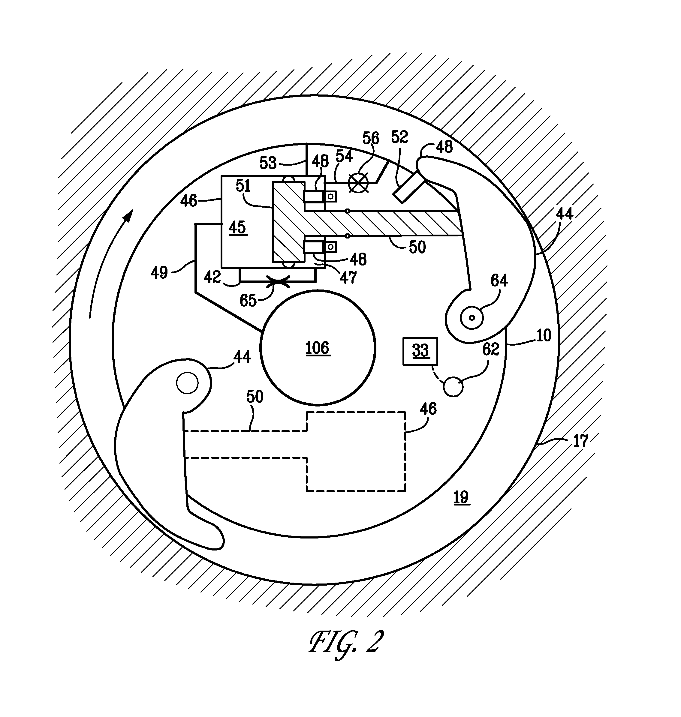
[0028]the torsional damping module 10 is shown in FIG. 2. The module 10 is coupled to the drill string 12 and rotates along with it. The module 10 comprises a chamber 46 in which one end 51 of a piston 50 is disposed. The other end of the piston 50 contacts a friction pad 44. The friction pad 44 pivots around pivot pin 64 so that extension of the piston 50 causes the friction pad 44 to extend radially outward by rotating around the pivot pin and engage the side of the bore hole 17 in the formation 16. A spring 52 is coupled to the friction pad 44 so as to bias the friction pad 44 into its retracted position. For purposes of illustration, FIG. 2 shows, in solid lines, a first friction pad 44 in its extended position, and, in dotted lines, a second friction pad 44 in its retracted position. However, as discussed further below, generally, all of the friction pads 44 in the damping module would extend or retract simultaneously. Also, although only two friction pad assemblies are shown i...

embodiment 10

[0044]A second embodiment of a damping module 10′ according to the invention is shown in FIG. 3. This embodiment functions in a manner similar to embodiment 10 described above. Module 10′ comprises a housing 122 through which extends a drive shaft 99 coupled to the module so that the module rotates with the drive shaft, which, in turn, is coupled to the drill string 12. The shaft 99 has a central passage 106 formed therein through which drilling mud flows as explained above. Passages 150 from a hydraulic system supply a hydraulic fluid that pressurizes cylinders 152 when valves in the hydraulic system (not shown) are activated by the processor 133 in response to high torsional vibration. The pressurization of the cylinders 152 actuates pistons 154, which causes friction pads 112 to rotate around pivot pins 158 and contact the bore hole 17, creating a damping force as explained above.

[0045]The system for actuating the pistons 154 is described more fully in U.S. Pat. No. 7,389,830, en...

third embodiment

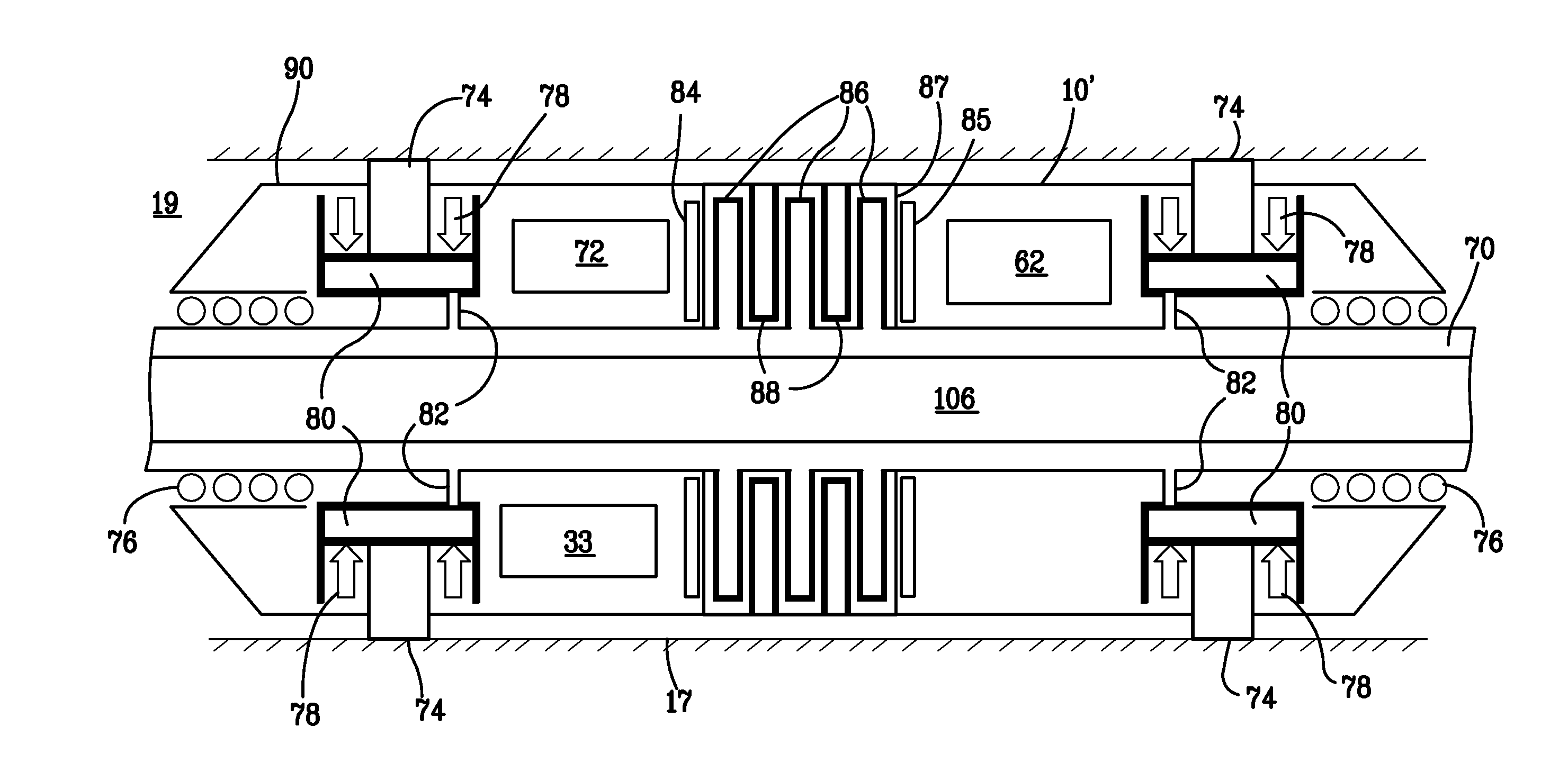
[0046]a torsional vibration damper 10″ is shown in FIG. 4. The module 10″ comprises a housing 90 that encloses a shaft 70. The shaft 70 is coupled to and rotates with the drill string 12 and is supported on bearings 76 on either side of the module housing 90. Drilling mud from the surface flows through the central passage 106 in the shaft 70, as discussed above. A plurality of piston chambers 80 are supported within the housing 90 and spaced around the circumference of the module 10 at fore and aft locations. A sliding piston 74 is supported within each chamber 80 and biased by springs 78 radially inward into a retracted position. The retraction of the pistons 74 facilitates sliding the drill string 12 into the bore hole 17 when the drill string is not rotating and no mud is being pumped through the drill string.

[0047]Passages 82 place the drilling mud flowing in the central passage 106 in flow communication with each of the chambers 80. Thus, whenever drilling is occurring, and dri...


PUM


Abstract

An apparatus and method for damping vibration, especially torsional vibration due to stick-slip, in a drill string, Sensors measure the instantaneous angular velocity of the drill string at one or more locations along the length of the drill string. One or more vibration damping modules are also spaced along the length of the drill string. When torsional vibration above a threshold is detected, the damping module imposes a reverse torque on the drill that dampens the torsional vibration. The reverse torque can be created by imparting a frictional resistance to the rotation of the drill string. The frictional resistance can be created externally, by extending friction pads from the damping module so that they contact the bore hole wall and drag along the bore hole as the drill string rotates, or internally by anchoring a housing mounted on the drill string to the wall of the bore hole and then imposing frictional resistance on a fluid, such as a magnetorheological fluid, flowing within the drill string.

Description

FIELD OF THE INVENTION[0001]The present invention relates to underground drilling, and more specifically to a system and a method for damping vibration, and especially torsional vibration, in a drill string drilling into an earthen formation.BACKGROUND OF THE INVENTION[0002]Underground drilling, such as gas, oil, or geothermal drilling, generally involves drilling a bore through a formation deep in the earth. Such bores are formed by connecting a drill bit to long sections of pipe, referred to as a “drill pipe,” so as to form an assembly commonly referred to as a “drill string.” The drill string extends from the surface to the bottom of the bore.[0003]The drill bit is rotated so that it advances into the earth, thereby forming the bore. In rotary drilling, the drill bit is rotated by rotating the drill string from the surface. Piston-operated pumps on the surface pump high-pressure fluid, referred to as “drilling mud,” through an internal passage in the drill string and out through ...

Claims


Application Information

Patent Timeline
Patent Type & Authority Applications(United States)
IPC IPC(8): E21B7/24
CPCE21B17/07E21B17/10E21B44/00
Inventor TURNER, WILLIAM EVANSHUTCHINSON, MARKBOSMAN, DIRKWASSELL, MARK ELLSWORTHPERRY, CARL ALLISONCOBERN, MARTIN E.
Owner APS TECH
Why Eureka
Try Eureka