
Wind flux concentration guiding device and engine room layout thereof

a technology of wind flux and guiding device, which is applied in the direction of machines/engines, transportation and packaging, branching pipes, etc., can solve the problems of limiting the cooling performance of the engine, and achieve the effects of increasing the inflow amount of wind, increasing the cooling performance, and increasing the performance of the intercooler

Active Publication Date: 2012-09-13
HYUNDAI MOTOR CO LTD +1
View PDF30 Cites 4 Cited by
  • Summary
  • Abstract
  • Description
  • Claims
  • Application Information

AI Technical Summary

Benefits of technology

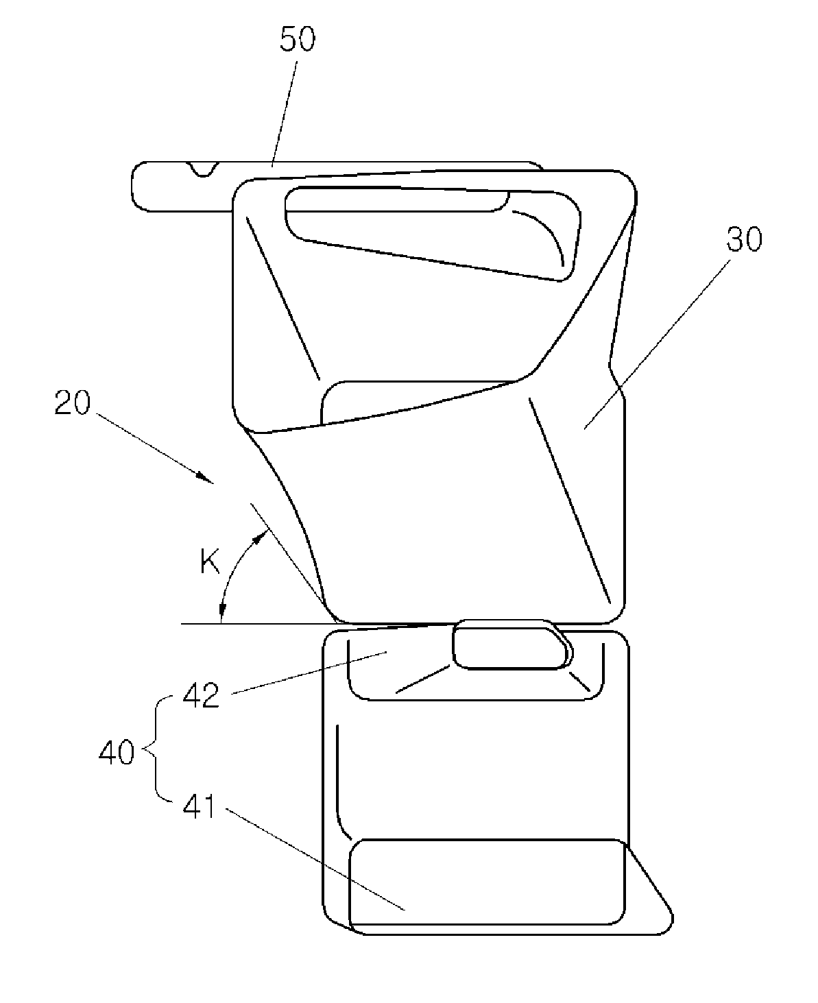
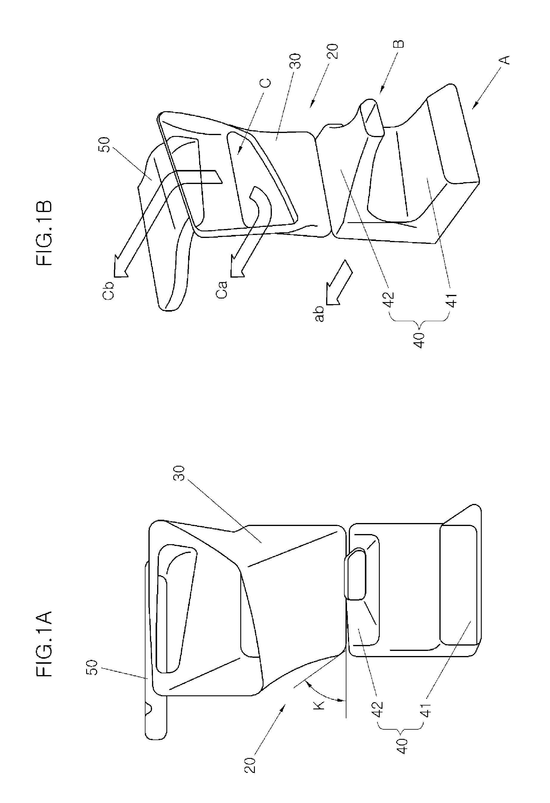
[0016]Various aspects of the present invention are directed to providing a wind flux concentration guiding device that can remarkably increase the inflow amount of wind without detracting the degree of freedom in designing of the external appearance of the front of a vehicle and increase cooling performance for a condenser and a radiator by concentrating the flow of wind to the condenser, radiator, and intercooler, and particularly, increase the performance of the intercooler in high efficiency only with the wind to fit the high-performance engine without upgrading the specifications of the intercooler.
[0029]The present invention has an advantage of considerably increasing cooling performance by increasing the inflow amount of wind flowing to a condenser, a radiator, and an intercooler, and particularly, of implementing high-efficiency operation of the intercooler, which is required for a high-performance engine, only with cooling of the wind.
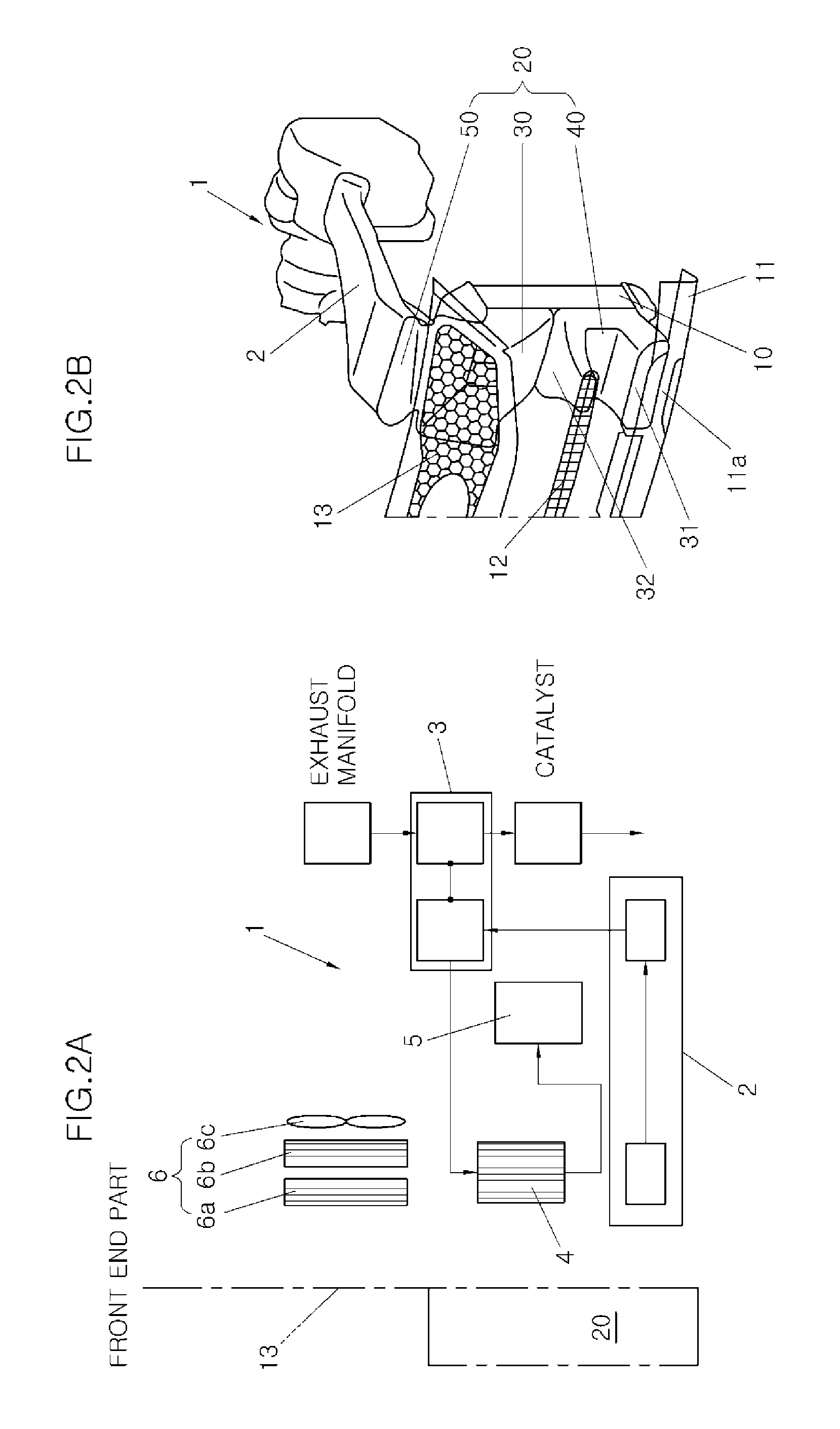
[0031]The present invention has an advantage of significantly increasing intake performance by directly sending some of wind flowing into the engine to the air intake, and optimizing the layout of the engine room by optimally designing the condenser, radiator, and intake system, using the flow of wind in a wind flux concentration guiding device, in one analysis system.

Problems solved by technology

Therefore, the open area of the front end part for increasing the inflow amount of wind is necessarily restricted in expanding by the degree of freedom of the external appearance and the restriction is inevitably accompanied with a limit in increasing the cooling performance of the intercooler only with the wind.

Method used


Image

  • Wind flux concentration guiding device and engine room layout thereof
  • Wind flux concentration guiding device and engine room layout thereof
  • Wind flux concentration guiding device and engine room layout thereof

Examples


Embodiment Construction

[0038]Reference will now be made in detail to various embodiments of the present invention(s), examples of which are illustrated in the accompanying drawings and described below. While the invention(s) will be described in conjunction with exemplary embodiments, it will be understood that present description is not intended to limit the invention(s) to those exemplary embodiments. On the contrary, the invention(s) is / are intended to cover not only the exemplary embodiments, but also various alternatives, modifications, equivalents and other embodiments, which may be included within the spirit and scope of the invention as defined by the appended claims.

[0039]Exemplary embodiments of the present invention are described hereafter in detail with reference to the accompanying drawings, and the exemplary embodiments can be achieved in various ways by those skilled in the art and the present invention is not limited to the exemplary embodiments.

[0040]Referring to FIG. 1A, a wind flux conc...


PUM


Abstract

An engine room layout using a wind flux concentration guiding device, may include an intake system having an air intake, a turbocharger, and an intercooler, and may be disposed in an engine room, a cooling module having a condenser and a radiator, a main duct that introduces wind passing through a front end part forming the front of the engine room and discharges the wind to the air intake and the intercooler, a sub-duct that introduces the wind passing through the front end part from different positions and discharges the wind to the intercooler, and a diverging duct that may be connected to a wind channel of the main duct to diverge some of the wind introduced into the main duct before the wind passes out of the main duct, and send the wind to the air intake.

Description

CROSS-REFERENCE TO RELATED APPLICATIONS[0001]The present application claims priority to Korean Patent Application Number 10-2011-0021223 filed Mar. 10, 2011, the entire contents of which application is incorporated herein for all purposes by this reference.BACKGROUND OF THE INVENTION[0002]1. Field of the Invention[0003]The present invention relates to a wind flux concentration guiding device, and more particularly, to a wind flux concentration guiding device that can appreciably increase cooling performance for an intercooler by increasing the inflow amount of wind, and an engine room layout with optimized layout.[0004]2. Description of Related Art[0005]In general, an air intake that sucks the external air passing through an air filter, an intake system that includes an intake manifold connected to a combustion chamber, a condenser of a cooling device, and a radiator of an engine cooling system are arranged around an engine disposed in an engine room.[0006]Unlike gasoline vehicles, ...

Claims


Application Information

Patent Timeline
IPC IPC(8): B60K11/08F16L41/00
CPCB60K11/04B60K11/08F01P2060/02F01P11/10F01P2001/005B60K13/02Y10T137/85938B62D25/08
Inventor NAM, JONGWOOLEE, JONGHOONKIM, WONSIKHAN, JONGWAN
Owner HYUNDAI MOTOR CO LTD
Learn More