Method of forming blown polymeric foam film

a polymer foam and film technology, applied in the field of polymer foam, can solve problems such as difficulty in maintaining a good cell structur

Active Publication Date: 2012-09-13
TREXEL
View PDF13 Cites 40 Cited by
  • Summary
  • Abstract
  • Description
  • Claims
  • Application Information

AI Technical Summary

Problems solved by technology

However, when blowing polymer foam films, it can be challenging to maintain a good cell structure because there is a tendency to distort the foam cells during the blowing process.

Method used


Image

  • Method of forming blown polymeric foam film
  • Method of forming blown polymeric foam film
  • Method of forming blown polymeric foam film

Examples


example

[0047]This example illustrates the production of a polymeric foam blown film according to techniques of the invention.

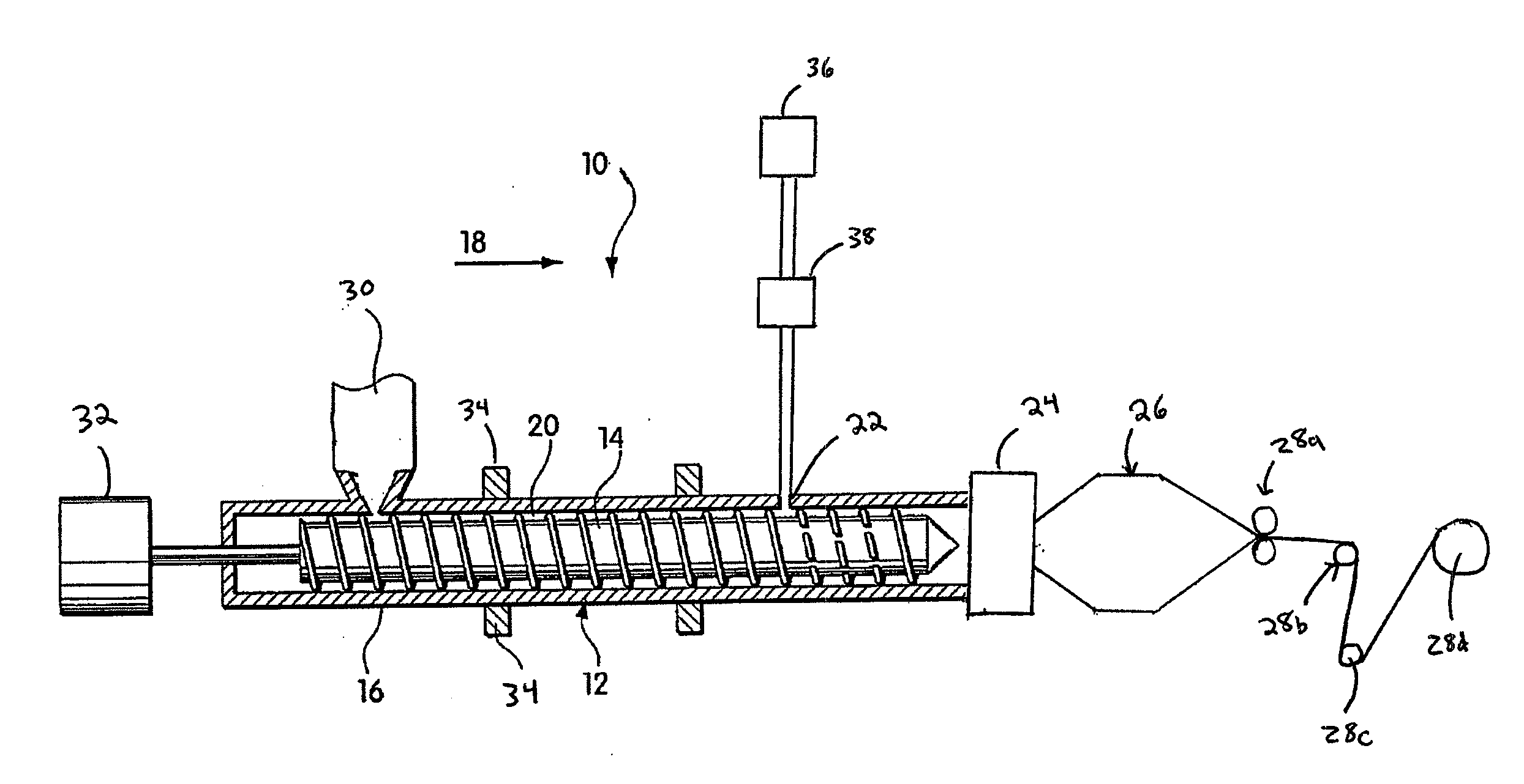
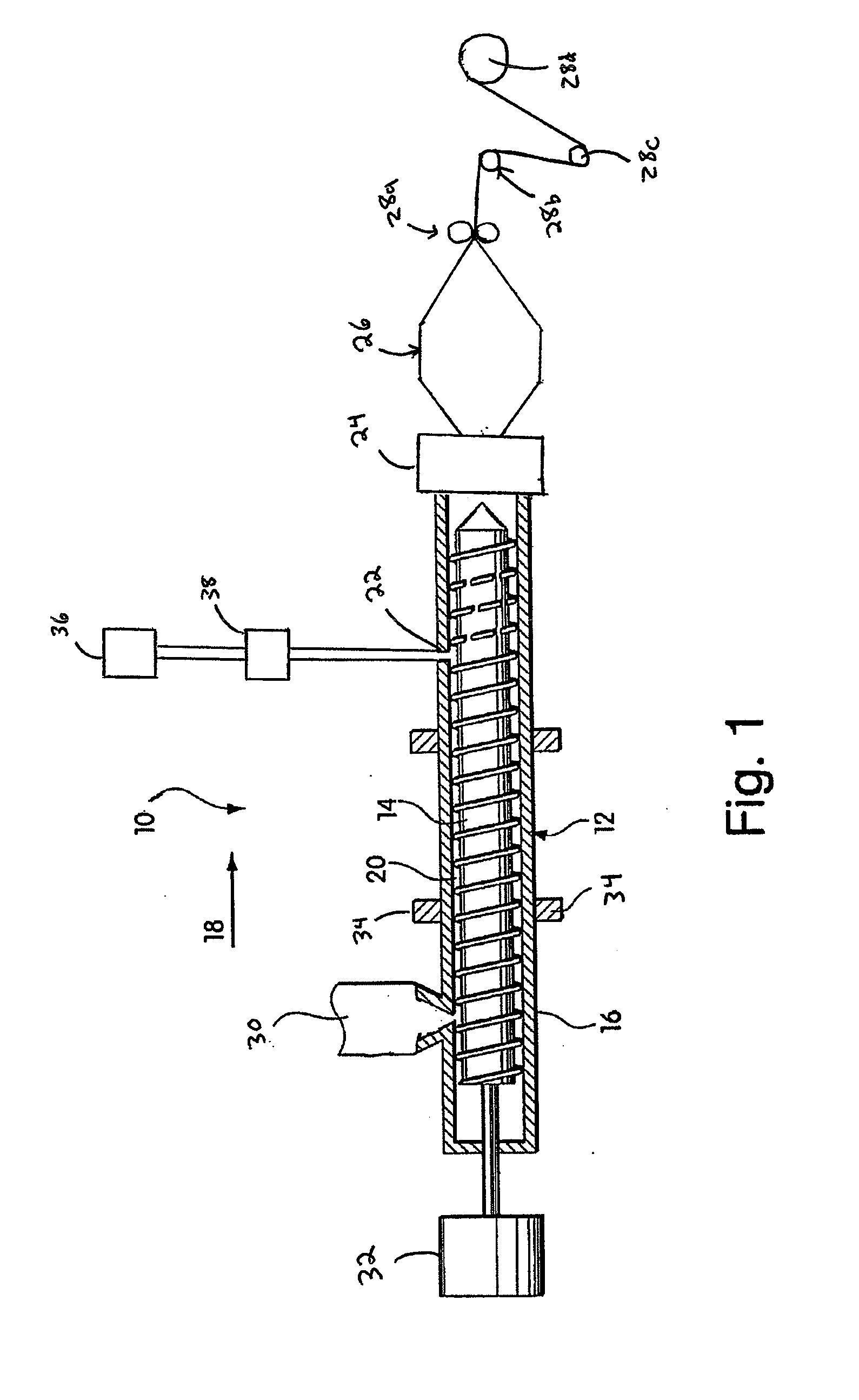
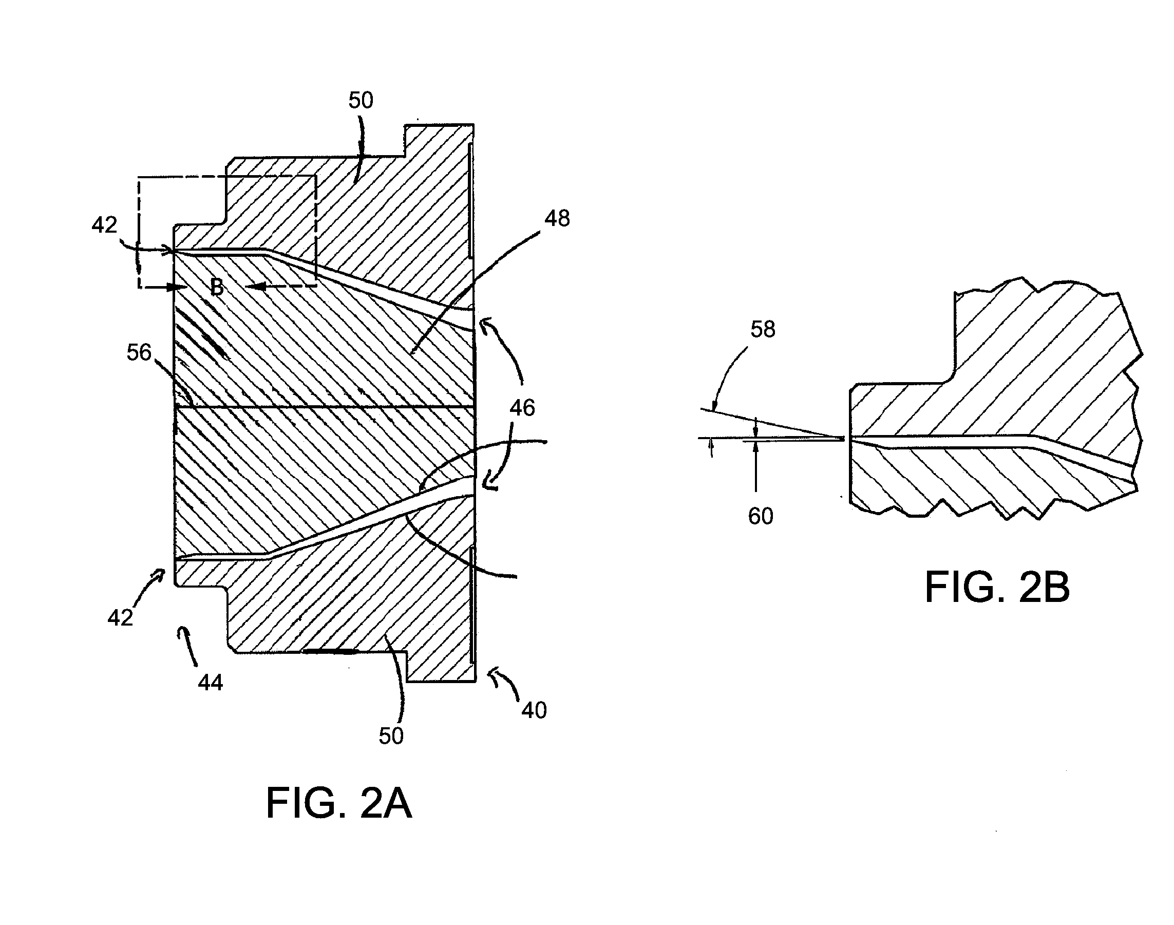
[0048]A stream of medium density polyethylene material (MDPE) was created in an extruder. Nitrogen was introduced through a blowing agent port into the stream to form a mixture of nitrogen and MDPE. The percentage of N2 was less than about 0.5% by weight of the mixture. The mixture was mixed within the extruder to form a single-phase solution. The solution was extruded through a die similar to the one illustrated in FIGS. 2A and 2B. The die had a taper angle of between 4° and 20° and the gap at its outlet was less than 0.012 inches. The annular extrudate was blown to form an MDPE foam film precursor. The film precursor was processed, including by a slitting operation, to form a blown MDPE foam film.

[0049]The blown foam film was characterized using SEM analysis. FIG. 4 is a copy of an SEM photo illustrating a representative section of the film. The average cell size o...


PUM

PropertyMeasurementUnit
angleaaaaaaaaaa
angleaaaaaaaaaa
densityaaaaaaaaaa

Abstract

A method of forming a blown polymeric foam film is described herein. As described further below, equipment design (e.g., die design) and processing conditions may be controlled to form blown films having desired characteristics.

Description

FIELD OF INVENTION[0001]The invention relates generally to polymeric foam and more particularly to a method of forming a blown polymeric foam film.BACKGROUND OF INVENTION[0002]Polymeric foams include a plurality of cells (or voids) formed within a polymer matrix. Microcellular foams (or microcellular materials) are polymeric foams which have very small cell sizes and high cell densities. By replacing solid plastic with voids, polymeric foams use less raw material than solid plastics for a given volume. Thus, raw material savings increase as the density of a foam decreases.[0003]Blown film extrusion is a common technique to make polymer films. The process generally involves extruding a tube of molten polymer through a die and inflating the tube to several times its initial diameter to form a thin film bubble. This bubble is then collapsed and formed into a film.[0004]Blown film generally has a better balance of mechanical properties than cast or extruded films because the film is dra...

Claims


Application Information

Patent Timeline
Patent Type & Authority Applications(United States)
IPC IPC(8): B29C47/14B29C48/305B29C48/10B29C48/11
CPCB29C47/0026B29C47/0057B29C47/065B29K2105/041B29C47/20B29C47/1072B29C47/1009B29C48/10B29C48/0018B29C48/21B29C48/286B29C48/295B29C48/32B29C48/11B29C48/09B29C48/2515B29C48/0012B29C48/1472B29C48/146B29C48/0017B29C55/28
Inventor LINDENFELZER, MARK E.ANDERSON, JERE R.DIX, SAMUEL E.
Owner TREXEL
Why Eureka
Try Eureka