Continuous Electroplating Apparatus with Assembled Modular Sections for Fabrications of Thin Film Solar Cells

Inactive Publication Date: 2012-09-13
WANG JIAXIONG
View PDF11 Cites 34 Cited by
  • Summary
  • Abstract
  • Description
  • Claims
  • Application Information

AI Technical Summary

Benefits of technology

[0009]The present invention provides a roll-to-roll or reel-to-reel flexible electroplating apparatus to deposit multiple layers of different metals on thin continuous sheets of conductive substrates such as stainless steels, aluminum and so on. This apparatus consists of a series of modular electroplating sections the lengths of which can be readily adjusted to meet the requirements of different current densities required by various plating bathes. In addition, the removable bath tanks can be simply assembled to different modular plating sections. For a multiple layers with different

Problems solved by technology

In such a case, changing a metal plating order may sig

Method used


Image

  • Continuous Electroplating Apparatus with Assembled Modular Sections for Fabrications of Thin Film Solar Cells
  • Continuous Electroplating Apparatus with Assembled Modular Sections for Fabrications of Thin Film Solar Cells

Examples


Example

Example 1

Electroplating of a Copper Layer onto a Molybdenum Surface Coated on a Stainless Steel Roll at a High Current Density

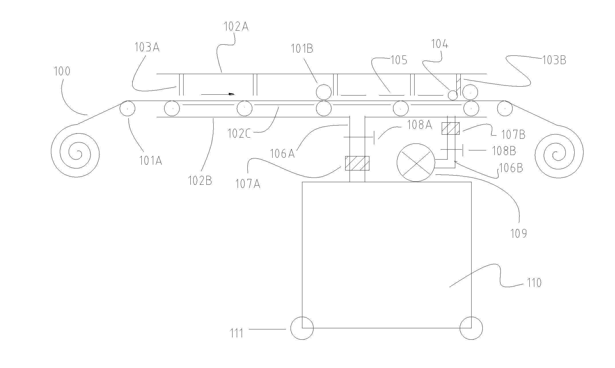
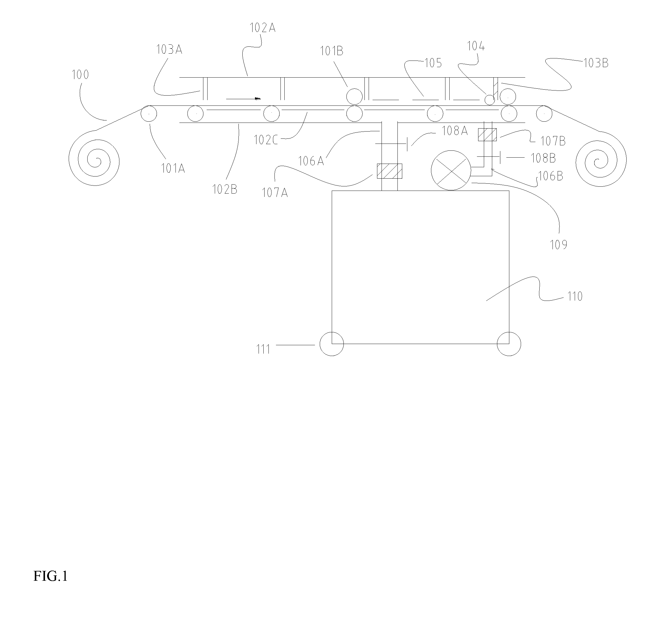
[0014]A one foot wide stainless steel roll coated with a molybdenum layer was loaded. It was delivered from left to right through an electroplating modular section as shown in FIG. 1 at a speed of 1 meter per minute. An aqueous electroplating copper solution containing 0.1 M Cu2+ in 6% H2SO4 was loaded into the tank 110, delivered into the top electroplating cell through the pump 109, the pipe 106B and the pipe 104, and then flowing back to the tank through the pipe 106B. To plate Cu at a high current density, a board was inserted into a pair of groove 103B that is close to the right wall 103A to build a short plating cell which might contain only one piece of the net anode module. A soft roller 101B was put outside the left of the top cell to avoid the solution flowing out. On the purpose of reducing gas generation and remain the Cu2+ concentration in the ba...

Example

Example 2

Electroplating of a Copper Layer onto a Molybdenum Surface Coated on a Stainless Steel Roll at a Low Current Density.

[0015]The same materials and the plating bath was applied in this example. To meet the requirement for a low plating current density, the length of the top plating cell was increased by placing the isolation board at a pair of grooves 101B far away from the right wall 101A. Several pieces of the net anode modules 105 were connected. No copper piece was used as a soluble anode in this case. The substrate delivery speed and the applied constant current were the same as described in Example 1. Since the top plating cell length was a few times longer than the one in Example 1, however, the plating was carried out at a much lower current density.

[0016]As described above, this apparatus can be manufactured to deposit Group IB-IIIA-VIA or Group IIB-VIA solar cell absorber stacks onto the flexible conductive substrates with different widths. It can also be used to el...


PUM

PropertyMeasurementUnit
Lengthaaaaaaaaaa
Lengthaaaaaaaaaa
Flexibilityaaaaaaaaaa

Abstract

An electroplating production line or apparatus that can be assembled with modular plating sections in a roll-to-roll or reel-to-reel continuous plating process is provided. The length of the plating cell for a modular plating section can be readily changed to fit different current densities required in a roll-to-roll or reel-to-reel process. In addition, the electrolyte solution tanks can be simply connected or disconnected from the modular plating sections and moved around. With these designs, a multiple layers of coating with different metals, semiconductors or their alloys can be electrodeposited on this production line or apparatus with a flexibility to easily change the plating orders of different materials. This apparatus is particularly useful in manufacturing Group IB-IIIA-VIA and Group IIB-VIA thin film solar cells such as CIGS and CdTe solar cells on flexible conductive substrates through a continuous roll-to-roll or reel-to-reel process.

Description

BACKGROUND[0001]1. Field of the Invention[0002]The present invention relates to a roll-to-roll or reel-to-reel electroplating production line that can be assembled to deposit multiple absorber layers of metal or alloy thin films to fabricate thin film solar cells based on the Group IB-IIIA-VIA or IIB-VIA polycrystalline compounds.[0003]2. Description of the Related Art[0004]With the development of global warming, environmental contaminations and exhausting of fossil fuels, solar cells have attracted more and more attentions as a leading green energy source. Although crystalline silicon based solar cells still dominate the solar cell world market today, thin film solar cells have shown a very promising future due to their low costs, flexibility and capability of large scale industrial manufacture. In this thin film solar cell family, the CIGS solar cells possess the highest conversion efficiency that is as high as 20%, higher than 16% efficiency of the CdTe ones. In the periodic tabl...

Claims


Application Information

Patent Timeline
IPC IPC(8): H01L31/0256C25D17/02C25D7/12
CPCC25D7/0621C25D7/0642C25D7/126C25D17/02Y02E10/543H01L31/0326H01L31/1828H01L31/188Y02E10/541H01L31/0322C25D7/12
Inventor WANG, JIAXIONG
Owner WANG JIAXIONG
Why Eureka
Try Eureka