Cooperative communications in cellular networks

a technology of cellular networks and cooperative communications, applied in the field of telecommunications, can solve the problems cooperative communications operate at the cost of high resource occupation, and limited number of antennas of mobile terminals, and achieve the effect of improving the performance of wireless communications

Inactive Publication Date: 2012-09-13
ALCATEL LUCENT SAS
View PDF7 Cites 93 Cited by
  • Summary
  • Abstract
  • Description
  • Claims
  • Application Information

AI Technical Summary

Benefits of technology

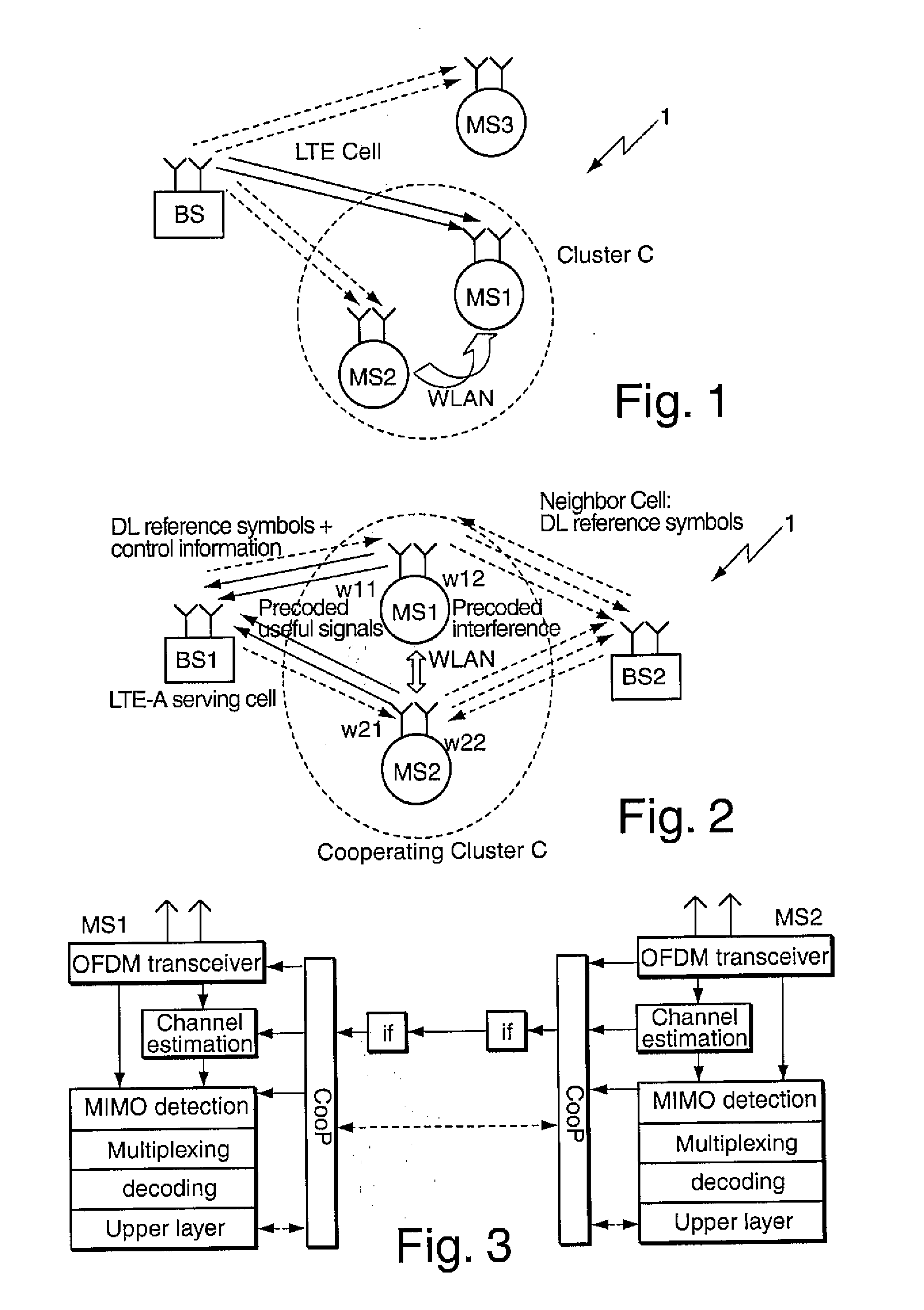
[0022]In a further variant, the mobile stations of the cluster are time synchronized, preferably using at least one of a time synchronization protocol, in particular a Precision Time Protocol, PTP (IEEE 1588), a Global Positioning System, GPS, and a synchronization mechanism inherent to the first and/or the second transmission technology. For the coordinated communication, a dedicated time synchronization protocol may be used, or synchronization mechanisms/protocols which are inherent to the first/second transmission technology may be employed. Also, a common time reference, e.g. provided by a GPS system, may be used. It will be understood that in general, all mobile stations of the cluster have to be synchronized to the cellular network and therefore have to listen to pilot symbols in order to measure the channel state. In this way, even when some mobile stations of the cluster have no data to transmit, they may assist the data transmission for other mobile stations of the cluster, and a proper time synchronization of the mobile stations can still be guaranteed.
[0023]A further aspect of the invention relates to a mobile station, adapted for

Problems solved by technology

However, cooperative communications may cause security issues as, typically, it is assumed that there is no restriction of partnership between the cooperating mobile terminals.
Hence, coo

Method used


Image

  • Cooperative communications in cellular networks
  • Cooperative communications in cellular networks

Examples


Embodiment Construction

[0037]The functions of the various elements shown in the Figures, including any functional blocks labeled as ‘processors’, may be provided through the use of dedicated hardware as well as hardware capable of executing software in association with appropriate software. When provided by a processor, the functions may be provided' by a single dedicated processor, by a single shared processor, or by a plurality of individual processors, some of which may be shared. Moreover, explicit use of the term ‘processor’ or ‘controller’ should not be construed to refer exclusively to hardware capable of executing software, and may implicitly include, without limitation, digital signal processor (DSP) hardware, network processor, application specific integrated circuit (ASIC), field programmable gate array (FPGA), read only memory (ROM) for storing software, random access memory (RAM), and non volatile storage. Other hardware, conventional and / or custom, may also be included. Similarly, any switch...


PUM


Abstract

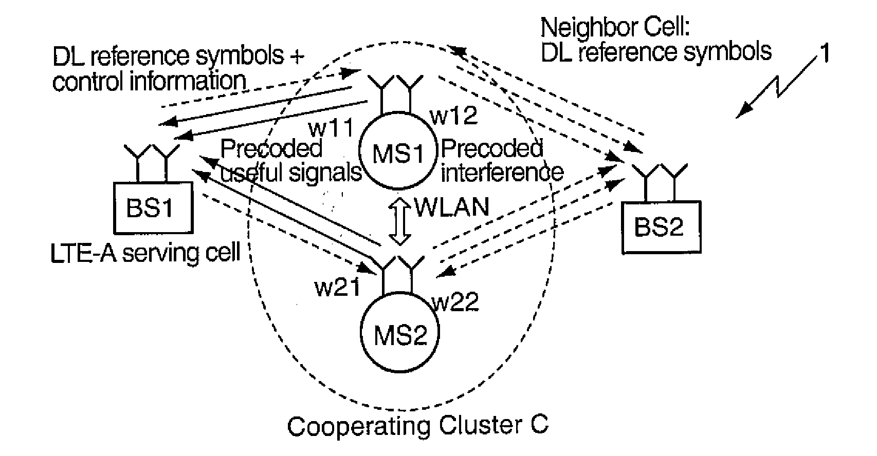
A method is provided for communications in a cellular network (1) comprising a plurality of mobile stations (MS1 to MS3) adapted for performing wireless communications with at least one base station (BS1, BS2) using a first transmission technology, the method comprising: forming a cooperating cluster (C) comprising two or more of the mobile stations (MS1, MS2), and performing short-range communications between the mobile stations (MS1, MS2) of the cooperating cluster (C) using a second transmission technology being different from the first transmission technology for improving, for at least one mobile station (MS1, MS2) of the cluster (C), the performance of the wireless communications with the base station (BS), preferably by using MIMO techniques for at least one of interference suppression and cancellation, in particular by using at least one of transmit precoding for uplink transmissions and receive antenna weighting for downlink reception. A mobile station (MS1, MS2) for forming a cooperating cluster (C), a cooperating cluster (C) comprising at least one such mobile station (MS1, MS2), and a cellular network (1) are also provided.

Description

FIELD OF THE INVENTION[0001]The invention relates to the field of telecommunications, and, more specifically, to cooperative communications between mobile stations adapted to perform wireless communications with at least one base station.BACKGROUND[0002]This section introduces aspects that may be helpful in facilitating a better understanding of the invention. Accordingly, the statements of this section are to be read in this light and are not to be understood as admissions about what is in the prior art or what is not in the prior art.[0003]The basic concept of cooperative communications is that two or more nodes, e.g. mobile terminals, may relay data mutually, the cooperative communications between the mobile terminals, being typically based on an air interface relay. The data received from the relay node may be taken as if transmitted from another base station. However, cooperative communications may cause security issues as, typically, it is assumed that there is no restriction ...

Claims


Application Information

Patent Timeline
IPC IPC(8): H04B7/00
CPCH04B7/026H04B7/0413H04B7/0689H04L27/2647H04L5/0035H04L25/03343H04B7/086H04L25/0224H04W56/001
Inventor CHEN, YUZHANG, BIJUNWILD, THORSTEN
Owner ALCATEL LUCENT SAS
Why Eureka
Try Eureka