Method for producing a pressure tank, a pressure tank and a pressure tank group

a technology of pressure tanks and pressure tanks, which is applied in the direction of mechanical equipment, vessel construction details, other domestic articles, etc., can solve the problems of restricted wrap angle, relatively high weight of such tanks, and relatively laborious art. , to achieve the effect of reducing the number of cycles of the method of invention, reducing the number of cycles, and ensuring the pre-stressing of the reinforcement fibers

Active Publication Date: 2012-09-20
DEUTSCHES ZENTRUM FUER LUFT & RAUMFAHRT EV
View PDF15 Cites 23 Cited by
  • Summary
  • Abstract
  • Description
  • Claims
  • Application Information

AI Technical Summary

Benefits of technology

[0029]In a further advantageous embodiment of the inventive method, the hollow body is expanded before and/or during impregnation and/or during curing by submitting the storage space to an excess pressure. Thereby, the close fit between the hollow body and the element or the elements of a textile sheet material can be improved and a certain degree of pre-stressing of the reinforcing fibers can be obtained. When using a molding device for the process of impregnating the reinforcing fibers, this measure can also contribute to an increase in the fiber volume content due to surplus resin being squeezed out from the gap between the hollow body and the molding device as a result of the expansion process. The impregnation process can be effected in a more controlled and rapid manner by comparatively large gap dimensions before t...

Problems solved by technology

In the case of metallic pressure tanks (e.g., tanks of the class CNG-1 meeting the standard ISO 11439), this can only be achieved by making the walls thereof sufficiently thick, whereby the weight of such tanks is relatively high.
The process of wrapping hollow bodies with a continuous...

Method used


Image

  • Method for producing a pressure tank, a pressure tank and a pressure tank group
  • Method for producing a pressure tank, a pressure tank and a pressure tank group
  • Method for producing a pressure tank, a pressure tank and a pressure tank group

Examples


Embodiment Construction

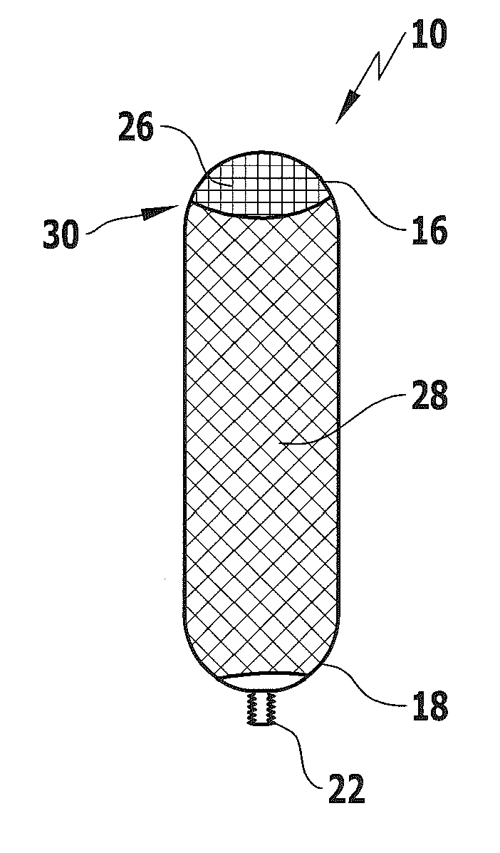
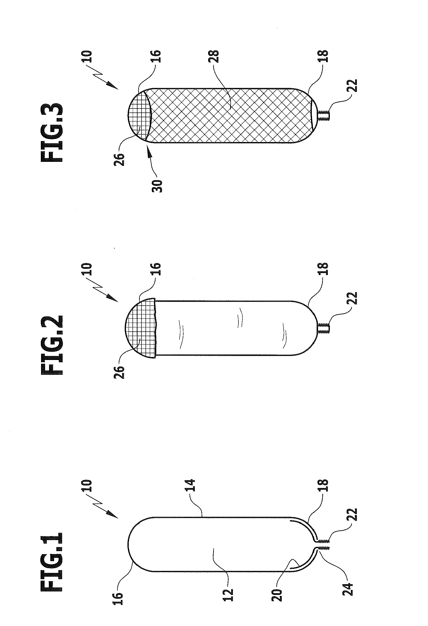
[0052]FIGS. 1 to 3 show schematically the sequence followed by the inventive method for producing a pressure tank. The starting point of the method is a hollow body 10 which defines a storage space 12 for a pressurized fluid (e.g., natural gas or hydrogen). The hollow body 10, which is shown in a sectional view in FIG. 1, has a substantially cylindrical shape having a circumferential surface 14 and two axial end regions 16 and 18 which are substantially hemispherical.

[0053]In this exemplary embodiment, the hollow body 10 is formed from a synthetic material, e.g., from HDPE. A likewise substantially hemispherical insert 20 made of a metallic material is arranged within the storage space 12 in the lower end region 18 of the hollow body 10. The insert 20 has a connector device 22 which protrudes out of the hollow body 10 through an opening 24 formed therein.

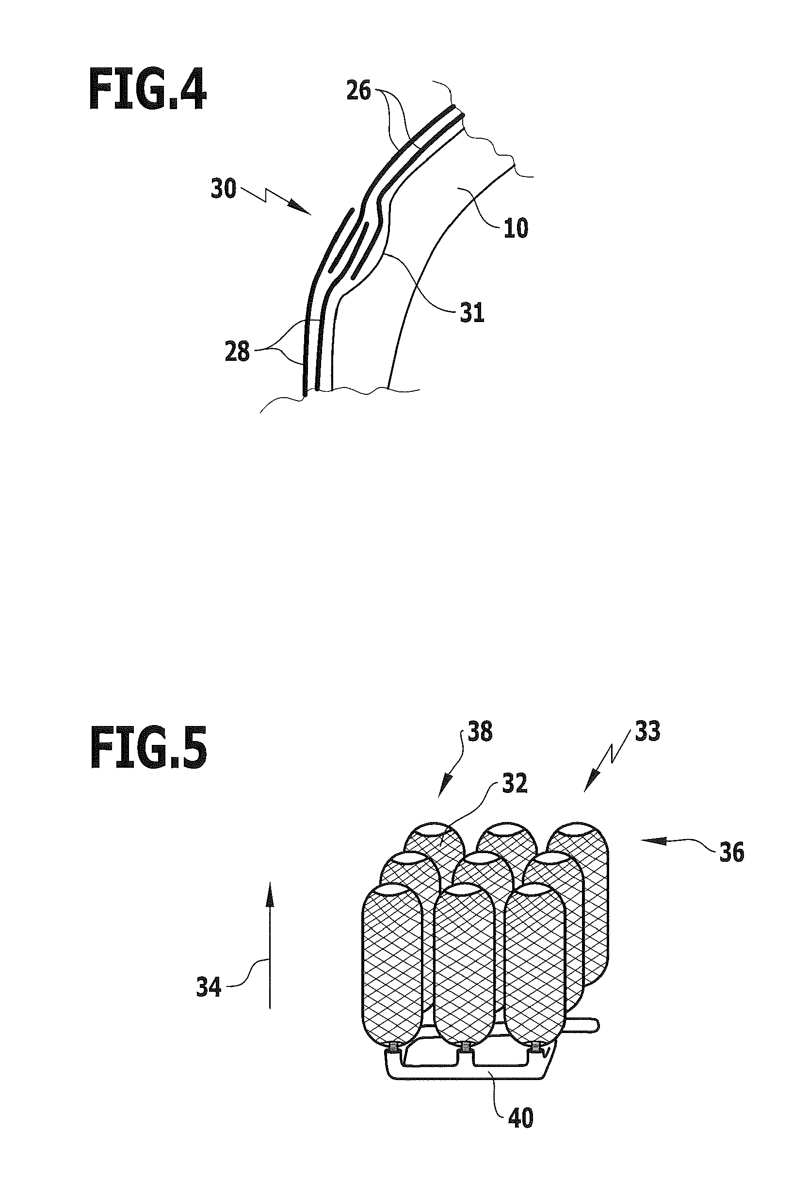
[0054]An element 26 of a textile sheet material is arranged on the upper end region 16 of the hollow body 10 in the course of the ...


PUM

PropertyMeasurementUnit
Pressureaaaaaaaaaa
Metallic bondaaaaaaaaaa

Abstract

The present invention provides a method for producing a pressure tank for holding a pressurized fluid, comprising the steps of providing a shaped body; arranging one or more elements of a textile sheet material of reinforcing fibers on the shaped body; impregnating the reinforcing fibers, before or after the arrangement of the element or elements on the shaped body, with a thermosetting or thermoplastic resin; and curing the resin to form a composite fiber material surrounding the shaped body. The invention also provides a pressure tank for holding a pressurized fluid, comprising a hollow body which defines a storage space for the fluid, and a composite fiber material surrounding the hollow body which comprises one or more elements of a textile sheet material. The invention further provides a pressure tank group comprising a plurality of such pressure tanks.

Description

CROSS-REFERENCE TO RELATED APPLICATION[0001]The present disclosure relates to the subject matter disclosed in German patent application number 10 2010 043 645.3 of Nov. 9, 2010, which is incorporated herein by reference in its entirety and for all purposes.BACKGROUND OF THE INVENTION[0002]The present invention relates to a method for producing a pressure tank for holding a pressurized fluid.[0003]The invention also relates to a pressure tank for holding a pressurized fluid, as well as to a pressure tank group.[0004]Pressure tanks are employed in, e.g., motor vehicles as a means for storing gaseous fuels such as natural gas or hydrogen. Due to the high pressure, the pressure tank must be able to withstand considerable forces. In the case of metallic pressure tanks (e.g., tanks of the class CNG-1 meeting the standard ISO 11439), this can only be achieved by making the walls thereof sufficiently thick, whereby the weight of such tanks is relatively high.[0005]A more favorable relations...

Claims


Application Information

Patent Timeline
IPC IPC(8): B32B37/02B32B37/12F17C1/06
CPCF17C1/04Y10T156/1002F17C2201/0152F17C2201/056F17C2203/0604F17C2203/0619F17C2203/0639F17C2203/066F17C2203/0663F17C2203/0675F17C2205/0142F17C2209/22F17C2221/012F17C2221/033F17C2223/0123F17C2223/036F17C2260/012F17C2260/013F17C2270/0168Y02E60/321B29C70/462B29C70/24F17C1/06F17C2203/011B29D22/003F17C2201/0109Y02E60/32
Inventor STRASSBURGER, PHILLIPKRISHNAMOORTHY, SIVAKUMARA KANNAPPANKRIESCHER, MICHAELERDL, GUNTHER
Owner DEUTSCHES ZENTRUM FUER LUFT & RAUMFAHRT EV
Why Eureka
Try Eureka